3 Installation
US SENTRY io 19
Installing the Modbus RTU Module
1. Check the controller to verify that its COM jack is not covered.
2. Insert the module’s connection plug into the jack until it is firmly seated (as
shown).
This Modbus RS485 is unidirectional and provides diagnostic and alarm data about the SENTRY io's alarm faults and
detector status to third party systems (such as PLC, DCS systems). View the Resources section in the SENTRY io Online
Help to download the Modbus address list.
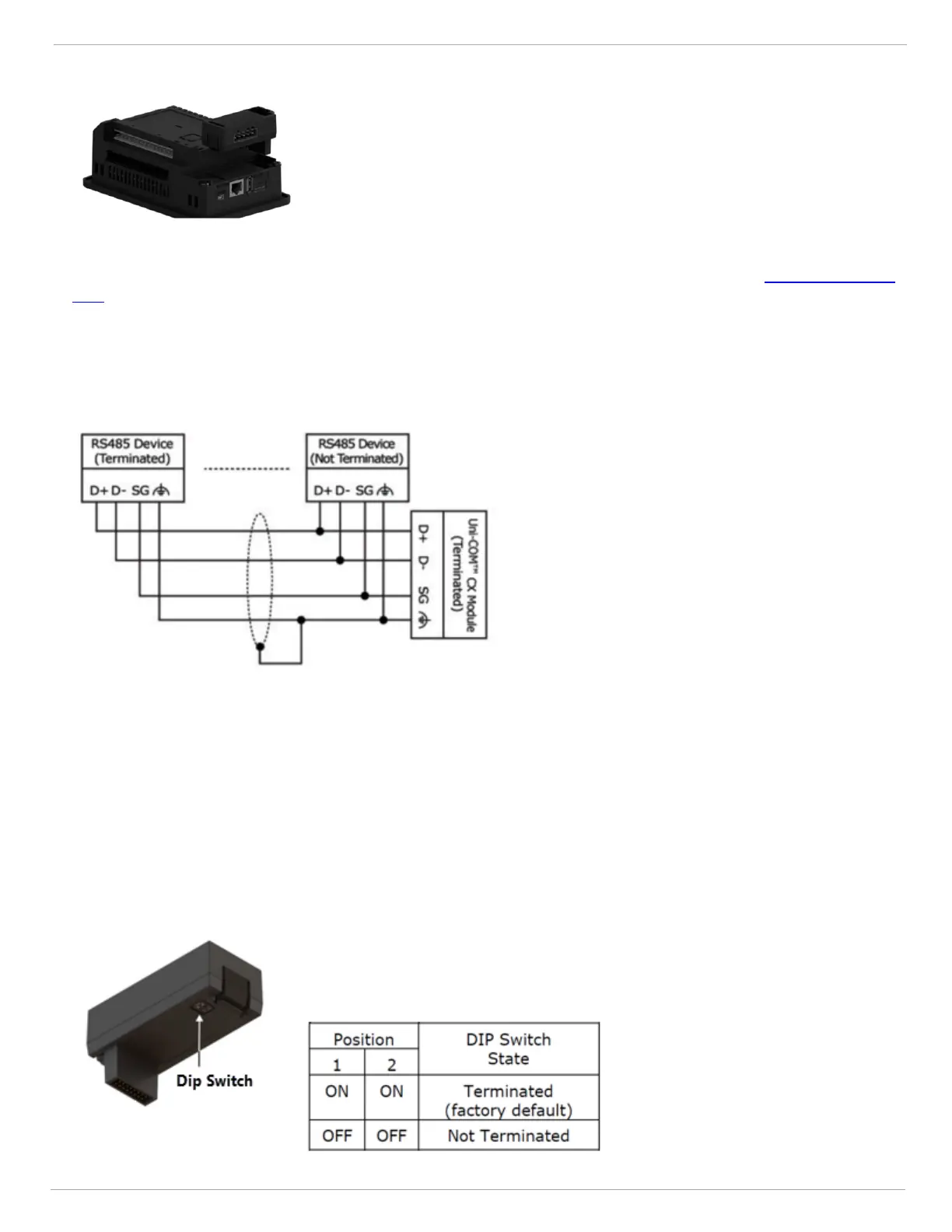
The Modbus RTU plug in module is shipped with a 4-pin RS485 terminal block. This connector is marked with a pin
assignment that is identical to the corresponding marking on the module. Termination should be made in accordance with
the diagram below.
RS485 Modbus Wiring Guidelines
l
Use shielded twisted-pair cable in compliance with EIA RS485 specifications.
l
When wiring each node, connect the cable shield to the functional ground point of the RS485 terminal block.
l
In order to avoid ground-loops, do not connect the RS485 functional ground terminal to the Earth of the SENTRY io
as it is internally connected to the SENTRY io's functional ground point.
RS485 Dip Switch Settings
Use the DIP switches shown in the table below to set the RS485. The device is shipped with both its DIP switches set to the
ON position; change settings to the OFF positions if there are no devices (PLC, HMIs, or DCSs) communicating on this
Modbus RTU network.