20 SENTRY io US
3 Installation
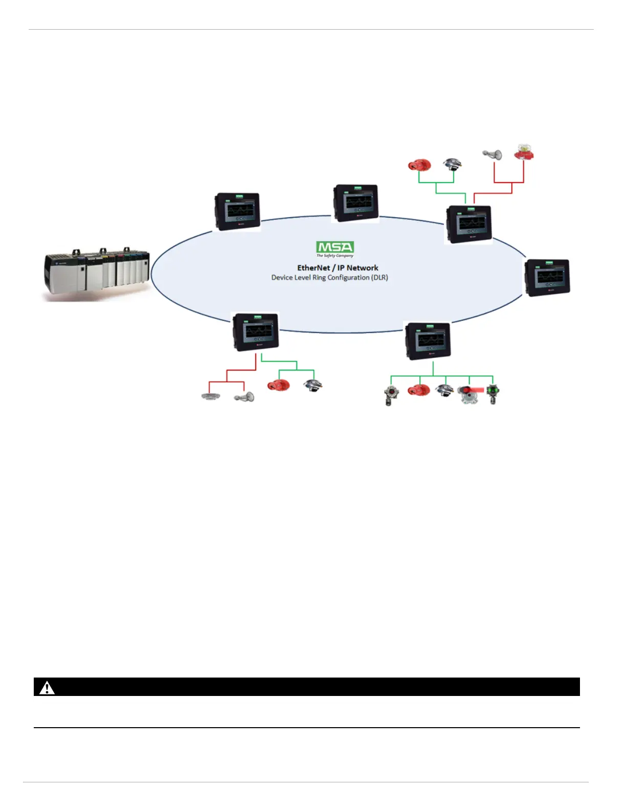
3.5.3 Device Level Ring (DLR)
The SENTRY io can be configured to become a stand-alone node on an EtherNet/IP network using Rockwell Automations
device level ring (DLR) protocol. This DLR communication provides a fault tolerant self-healing ring network that is capable
of being run over Ethernet cable or multi-mode fiber optics.
This topology is detailed below, and can be utilized with MSA’s HazardWatch platform. Please consult the factory for
assistance with this configuration.
3.6 Remote Displays
SENTRY io has the ability to support a remote display over Ethernet. A remote display will act and function the same way
as the primary SENTRY io display. Both the primary and remote displays will have the ability to function simultaneously.
To establish a remote display you must install an Ethernet link between the main SENTRY io controller and the remote
display. This link can either be over CAT 6 cable (max distance 100 meters) or via multi-mode fiber optic cable (max
distance 2 km). If the single Ethernet is already being utilized for other communications (such as Modbus TCP/IP or MSA
Cloud connection) or you are using a fiber link, then a supplemental Ethernet Switch will need to be provided.
Remote Display Power
The remote display must be sourced with its own 24 VDC power source. This remote display draws 1 amp at 24 VDC.
Establish Communication
To establish communication between the SENTRY io and remote display, please contact MSA Customer Support.
3.7 Wiring and Grounding
Refer to the Installation Outline drawing (SK3015-1071) for details on the wiring requirements for the SENTRY io.
WARNING!
Ensure the SENTRY io chassis is connected to the earth ground at the groundlug.
Failure to follow this warning can result in serious personal injury or death.