English
Tester MS016
24
4.2. Diagnostics of Lamp-type voltage regulators
1. Connect the voltage regulator as described in item 4.1.
2. Enter the menu for voltage regulator type selection, select the nominal voltage (12V or 24V) and
activate the test mode for Lamp-type regulators.
3. Upon activation, stabilizing voltage must set in the range from 14 to14.8 volts for 12V voltage
regulators and from 28 to 29.8 volts - for 24V regulators, and must correspond to the voltage
regulator characteristics.
4. Turn off simulation of the alternator rotation by pressing K15 and setting rpm to zero – the
control lamp indicator (Fig.10, n.10) will light up. Press K15 again to restart simulation, the control
lamp indicator must go out.
5. If the voltage regulator is equipped with terminal S, press SENSE to check its operability – the
stabilizing voltage must increase. Press SENSE once again – the stabilizing voltage must decrease
to its initial values.
6. Failure to perform as described in sub-items 3-5 signals the voltage regulator malfunction.
7. Press BACK to exit the test mode. Disconnect the clips form the voltage regulator.
4.3. Diagnostics of voltage regulators of RLO, RVC, and C
KOREA types
1. Connect the voltage regulator as described in item 4.1.
2. Enter the menu for voltage regulator type selection (Fig.9), select the nominal voltage and
activate the test mode that corresponds to the type of the tested voltage regulator.
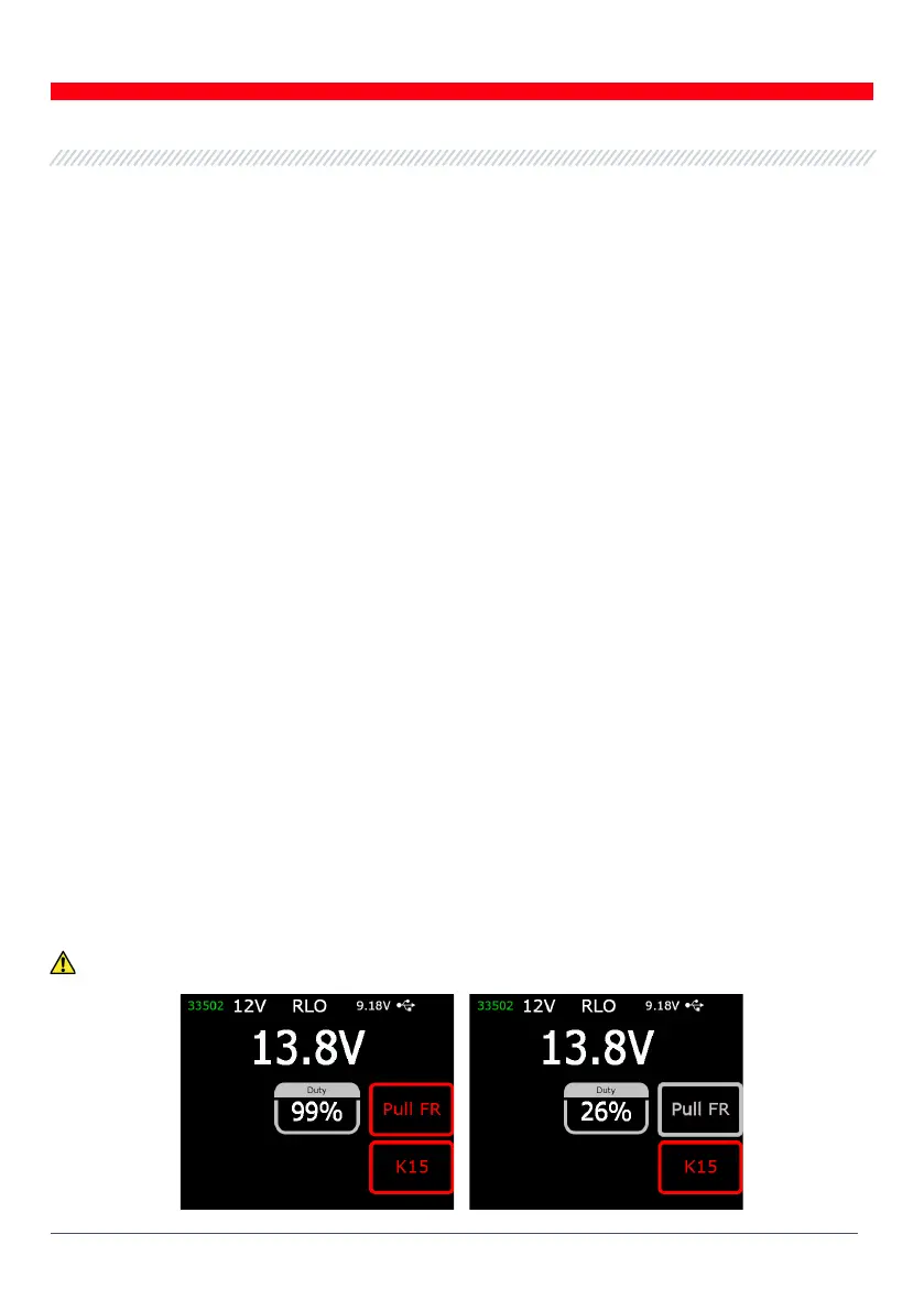
3. Upon diagnostic mode activation, the stabilizing voltage must set at 13.8V, the allowable
deviation is ±0,2V.
WARNING! If “Duty” value is 99%, press “Pull FR” to switch over.