English
Tester MS016
12
Press the button with the required type of the voltage regulator to enter the alternator/voltage
regulator test mode.
Press to return to the main menu.
2.1. Test modes menu
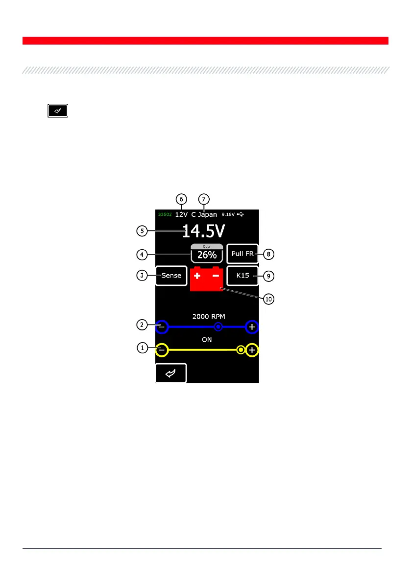
Upon entering the test mode for voltage regulators, the following information will appear on the
screen (Fig.10):
Figure 10 - Diagnostic screen information
1 – Preset stabilizing voltage (for controlled voltage regulators);
2 – Preset rpm (this parameter will not be displayed in alternator test mode);
3* – Button to check the SENSE terminal through which the voltage regulator measures the battery
voltage (red indication: the voltage across SENSE is lower by 0.5V-0.7V than the voltage across B+);
4 - Duty cycle of PWM signal received through FR channel (the proportion of the rotor winding
“on” time);
5 – Measured stabilizing voltage;