English
Operation manual
13
6 – Test mode nominal voltage;
7 – Voltage regulator type;
8* – Button to switch the mode of data readout through FR channel;
9* – Switch starting button;
10 - Alternator control lamp indicator (for voltage regulators that directly control the lamp).
* Color indication of the button:
red – ON;
white – OFF.
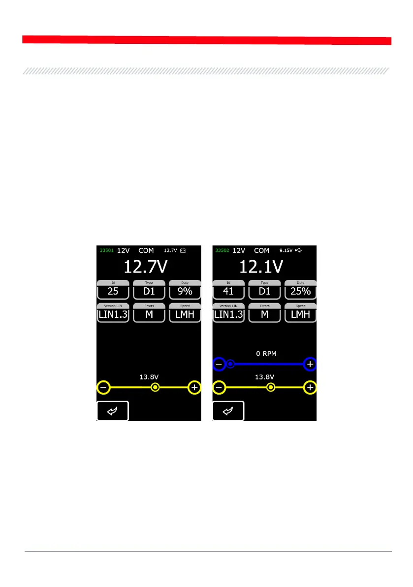
The diagnostic screen for voltage regulators of COM type displays the following information:
alternator voltage regulator
Figure 11 - Diagnostic screen for alternators/voltage regulators (12/24V) of COM type
„ID” - voltage regulator identification number. The engine control unit identifies the type of the
installed alternator by this number;
„Type” – voltage regulator type. The type codes of voltage regulators operating under LIN protocol
are as follows: A1, A2, A3, A4, B1, B2, B3, B4, C3, D1, D2, E1;
„Duty” - PWM signal duty cycle (the proportion of the rotor winding “on” time);