English
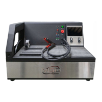
Tester MS016
26
4. Adjust the preset stabilizing voltage in the range from 13.2 to 14.5 volts. The measured voltage
must vary in proportion to the preset one.
5. Press BACK to exit the test mode. Disconnect the clips from the voltage regulator.
6. Failure to perform as described in sub-items 3-4 signals the voltage regulator malfunction.
4.6. Diagnostics of 12/24V voltage regulators of COM type
1. Connect the voltage regulator as described in item 4.1.
2. Enter the voltage regulator type selection mode, select the nominal voltage (12 or 24 volts) and
activate the test mode for COM voltage regulators.
3. Wait for the tester to read-out data. As soon as the values are displayed in ID, Version LIN, and
Type boxes we can proceed to testing.
3.1. After the data read-out is completed, the stabilizing voltage must set at 13.8V. The allowable
deviation is ±0,2V.
4. Set rpm to zero, the M value must appear in box ERRORS. As soon as the alternator speed
increases up to 800-1200 rpm, M is no longer displayed in the box ERRORS. It means, the system
of voltage regulator self-diagnosis is fault-free.
4.1 The E value displayed in box ERRORS upon speeding up the rotation to 1200 rpm, signals
electrical fault of the voltage regulator. At this point any further diagnostics makes no sense.
5. Change the preset stabilizing voltage in the range from minimum to maximum values. The
measured stabilizing voltage must vary in proportion to it.
6. Failure to perform as described in sub-items 3-5 signals the voltage regulator malfunction.
7. Press BACK to exit the test mode. Disconnect the clips form the voltage regulator
5. ALTERNATOR TESTING
Alternator testing on a vehicle is performed as follows:
WARNING! The tester does not allow the diagnostics of alternators without voltage regulators.
1. Search the information on markings of the alternator terminals by the voltage regulator OEM
number. Identify the alternator type by the contacts of the alternator terminals and based on the
information set out in Appendices 1 and 2.