English
Operation manual
27
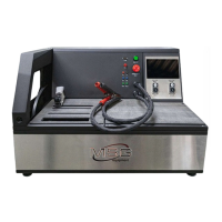
2. Connect the tester to the alternator observing the markings of cable MS-33501 (see
Section 1). Follow the instructions set out in Appendix 1.
2.1. Connect a cable clip “В+” to a positive terminal of the alternator and a cable clip “B-“ - either
to the alternator body or to the battery negative terminal. Powered by a battery, the tester will
be on and the main menu will be displayed.
2.2. Connect the appropriate clips of cable MS-33501 to the pins of the alternator terminals.
3. In the tester menu select the test mode for alternators (Fig.7, n.3) and then, select the alternator
type (Fig.9). The tester will switch over to the test mode.
3.1* Upon activation of the test mode, the control lamp indicator must light up.
* This does not apply to the alternators of SIG and P/D types.
3.2 If this is the alternator with COM terminal, wait for the tester to readout the data. As soon as
the values appear in ID, Version LIN, and Type boxes, proceed to testing.
4. Start the vehicle engine and turn the load off. Wait for it to run steadily at idle speed. The
stabilizing voltage shall set at 13.8V, the allowable deviation is ±0,2V.
4.1 The stabilizing voltage for Lamp-type alternators must set as follows: for 12V alternators - in
the range from 14 to 14.8 volts, for 48V alternators – from 28 to 29.8 volts.
4.2 The stabilizing voltage for alternators of C JAPAN type must set in the range from 14 to
14.5 volts.
5**. Change the stabilizing voltage in the range from 13.2 to 14.8 volts. The measured voltage must
vary in proportion.
** This does not apply to Lamp-type alternators.
5.1 When testing alternators of C JAPAN type, switch the preset stabilizing voltage to OFF. The
measured stabilizing voltage must set in the range from 12 to 12.7 volts.
6. Set the alternator voltage in the range from 13.2 to 14.8 volts. For C JAPAN alternators, switch
the preset voltage to ON. Increase the engine crankshaft rotation speed to medium. The measured
voltage must not change (the deviation by ±0,2V, is within the norm).
7. Without reducing the engine crankshaft speed, increase the load on the alternator by switching
on headlights and other lights. The voltage must not change (the voltage can reduce no more than
by 0.3V from the preset one).
8. Stop the engine.
9. Disconnect the cable clips from the alternator.
10. Failure to perform as described in sub-items 2.1, 3-7 indicates the voltage regulator
malfunction.