Electrical
99
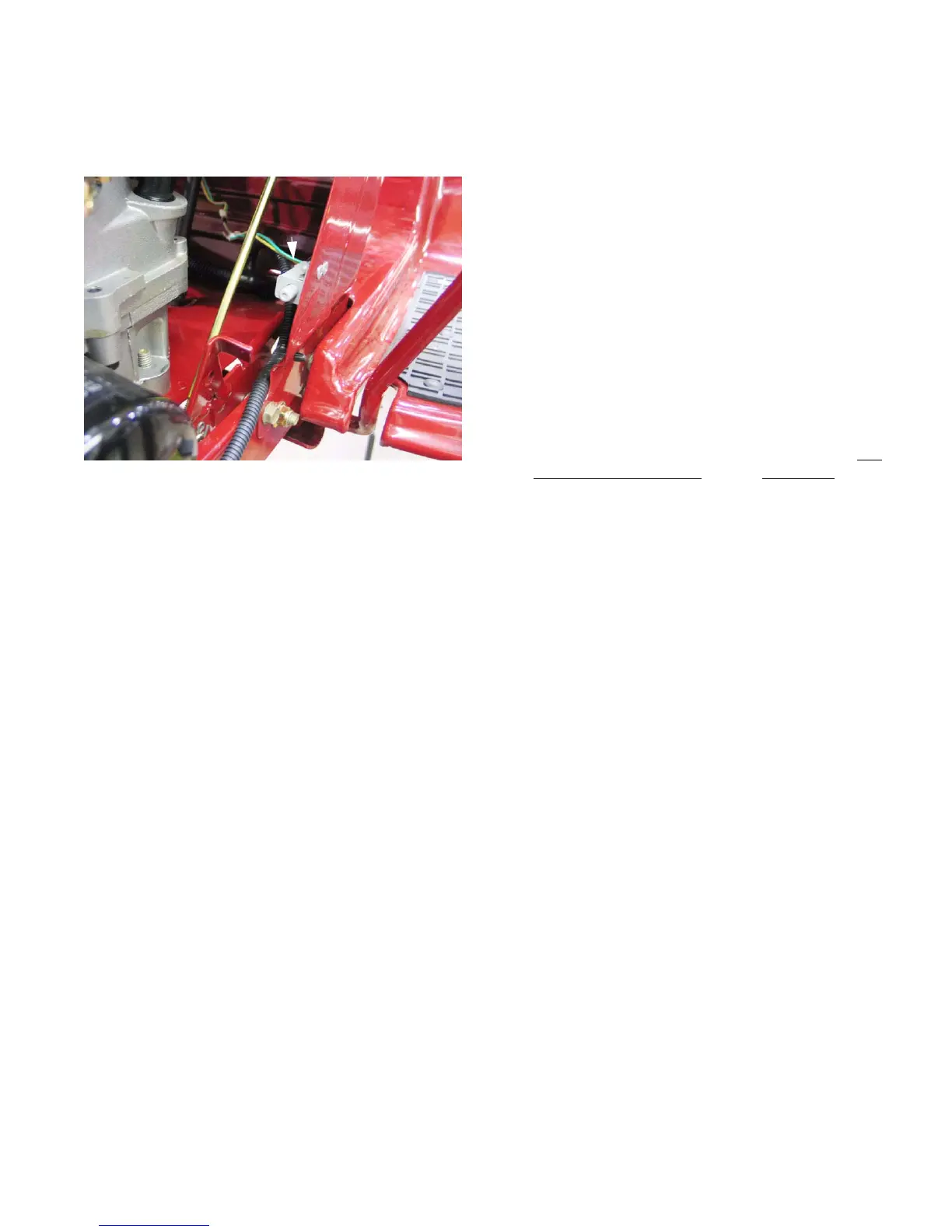
Park Brake Switch
• The Park Brake Switch is riveted inside the left
front edge of the dash panel.
See Figure 7.11.
• The switch contains two sets of contacts, one set
normally open (NO), and one set normally closed
(NC). Only the normally open set is used in this
application.
• The switch plunger is extended (contacts open)
when the parking brake is released: “RUN” posi
-
tion on the label.
• The plunger is depressed (contacts closed) when
the parking brake is applied: “ON” position on the
label.
• To insure that the correct spade terminals on the
switch are tested, it may be best to identify the
yel-
low wire with white trace and the green wire that
connect to the switch where they enter the connec
-
tor for the RMC module, and test from that point.
• When the park brake is set, this switch sends a ground signal to the RMC module. The module responds
by turning-off and disarming itself.
NOTE: Once the operator has set the parking brake, they may leave the seat of the tractor while the engine
continues to run. Because the tractor cannot tell if the same operator has returned to the seat when
operation resumes, the module must be re-set (armed) and turned-on by the operator who is currently
in the seat.
Figure 7.11
Park
brake
switch
FOR DISCOUNT PARTS CALL 606-678-9623 OR 606-561-4983
www.mymowerparts.com
 Loading...