700 Series Lawn Tractor
78
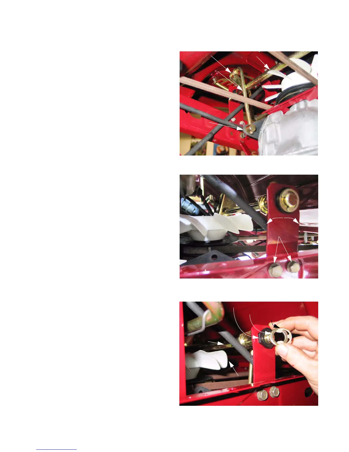
Transaxle control linkage
The lever that controls the ground speed and direction
of travel is located on the right rear fender.
The lever rotates a cross-shaft and bell crank. An
adjustable rod connects the bell crank to the input arm on
the left side of the transaxle.
See Figure 6.8.
The input arm on the transaxle will return to neutral
when the rod is disconnected. The rod length should be
adjusted so that the neutral position of the control lever on
the fender corresponds with neutral position of the input
arm.
• If mis-adjusted, the tractor will “creep” in neutral, or
lurch as soon as the brake is released, even though
the control lever is in neutral.
• If one end of the rod is disconnected, with the con-
trol lever in neutral, the centering action of the input
arm should not draw the end of the rod a way from
the hole it connects to.
• Lengthen or shorten the rod as necessary to adjust,
by threading it into or out of the ferrule.
• Reconnect the rod and test the operation of the link-
age and the tractor’s safety features before return-
ing the tractor to service.
NOTE: The pitch on the threads of the rod is 16
threads per inch. If an adjustment of less
than 1/16” is needed, the bolts that secure
the mounting bracket to the frame can be
loosened slightly for adjustment.
See Figure 6.9.
• The bracket can be budged one way or the other,
within the amount of travel allowed by the bolt holes
in the frame, to effect an adjustment.
• Once adjustment has been made, tighten the
bracket bolts.
NOTE: If the control lever develops enough play
that it becomes imprecise, the plastic hex
bushings that support the cross shaft are
easily replaced.
See Figure 6.10.
1. Remove the “E” clip and flat washer from the shaft.
2. Remove and replace the bushing.
Figure 6.8
Bell crank Cross shaft
Adjustable rod
Input arm
Figure 6.9
Bracket
bolts
Adjustment
Figure 6.10
Hex bushing
Flat washer
E-ring
Cross shaft
Fan
FOR DISCOUNT PARTS CALL 606-678-9623 OR 606-561-4983
www.mymowerparts.com
 Loading...