Hydrostatic Transaxles
85
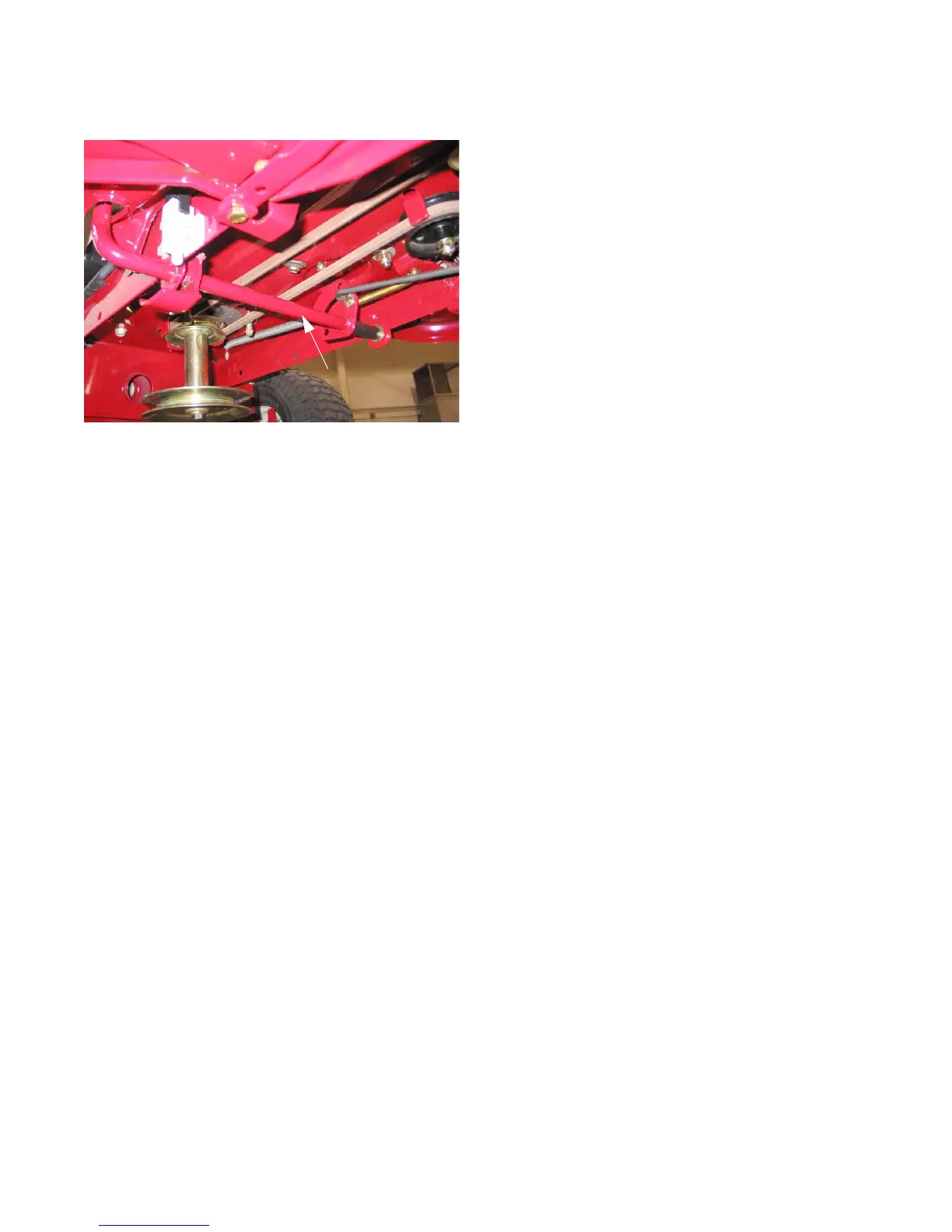
Brake pedal assembly
1. Remove the cutting deck to gain access to the link-
age. See Figure 6.24.
2. Mark or make note of the linkage connections and
orientations relative to the brake pedal assembly.
3. Disconnect the extension spring that reaches forward
from the brake pedal assembly
4. Remove and discard the cotter pins that secure the
brake rod and the tensioner pulley control rod to the
brake pedal assembly. Disconnect the rods.
5. Remove the pedal support brackets from the frame
using a 1/2” wrench, and lower the pedal assembly
out of the tractor.
6. Brake pedal assembly installation can be accom-
plished by reversing the removal process.
NOTE: Use new cotter pins on reassembly.
NOTE: Confirm correct operation of the brake / clutch pedal mechanism before returning the mower to ser-
vice.
Figure 6.24
Brake pedal assembly
FOR DISCOUNT PARTS CALL 606-678-9623 OR 606-561-4983
www.mymowerparts.com
 Loading...