Electrical
111
Charging circuit
All MTD tractors have a charging circuit, however the charging circuit will very from engine to engine. This sec-
tion will cover some of the basic theory and troubleshoot procedures for charging circuits.
IMPORTANT: Refer to the engine manufacturer for specific values and testing procedures.
All charging systems have three main component:
• Alternator
• Rectifier or a rectifier/regulator
•Battery
NOTE: This section will cover the alternator and the rectifier. The battery is covered in a separate section
towards the end of this chapter.
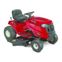
Alternator
The alternator is composed of two parts:
See Figure 7.27.
• The stator - named so because it remains station-
ary, is composed of copper coils wrapped around
iron cores.
• The rotor - named so because it rotates around the
stator, is composed of magnets mounted to the
underside of the flywheel.
1. When the engine is running, the magnets attached to
the underside of the flywheel induce an A.C. (Alter
-
nating Current) in the stator that is mounted beneath
the flywheel.
2. The A.C. voltage leaves and returns to the stator
through a rectifier.
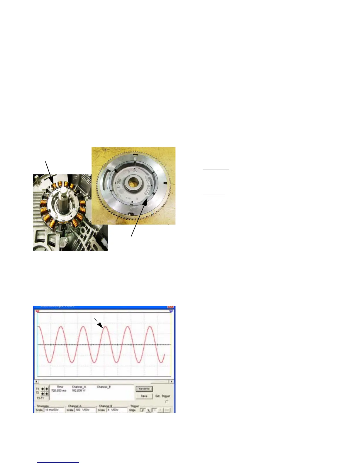
Rectifiers
The voltage coming out of the stator is AC, that means
it is constantly changing polarity. If an oscilloscope is con-
nected to the output voltage, a sine wave would be seen.
See Figure 7.28.
A rectifier is a devise that converts AC voltage into DC
voltage. The are two types of rectifiers commonly used on
lawn tractors:
•A half wave rectifier
•A full wave bridge rectifier
Stator
Rotor
(magnets in recess)
Figure 7.27
Figure 7.28
Sine wave
+
-
0
FOR DISCOUNT PARTS CALL 606-678-9623 OR 606-561-4983
www.mymowerparts.com
 Loading...