Home
MTD
Tractor
700 Series
MTD 700 Series Shop Manual
4
of 1
of 1 rating
150 pages
Give review
Manual
Specs
To Next Page
To Next Page
To Previous Page
To Previous Page
Loading...
Medium Frame 2 & 3
Stage Snow Throwers
12
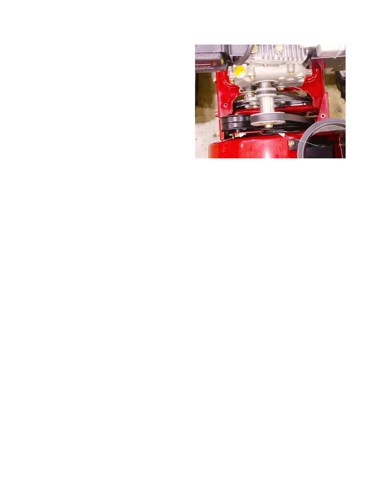
7.
Detach
the spring end of the cable from the Idler
Pulley Bracket. See F
igure 2.13.
8.
Install the cable
by following
the previous s
teps in
reverse or
der
.
NOTE:
When attach
ing he spring end of the cable,
the open s
ide of the s
pring faces
the engine.
9.
T
est
run the snow thrower in a safe area before
returning it to service.
Figure 2.13
Idler Pulley Bracket
Auger Cable
15
17
Table of Contents
Default Chapter
3
Table of Contents
3
Chapter 1: Introduction
5
Professional Service Manual Intent
5
Safety
5
Fasteners
7
Assembly Instructions
7
Identifying Snow Thrower Series
7
Understanding Model and Serial Numbers
8
Chapter 2: Belts and Cables
11
Auger Belt
11
Drive Belt
14
Auger Control Cable
15
Drive Clutch Control Cable
17
Auger and Drive Cable Adjustments (500, 600 and 3-Wheel Track Drives)
18
Auger Cable Adjustments (2-Wheel Track Drives)
19
Speed Selector Cable
20
Speed Selector Rod
22
Auger and Drive Lever Interlock
24
Chapter 3: 500 Series Drive System
27
Axle Assemblies
27
Hex Drive Shaft
30
Planetary Gears
31
Chapter 4: 600 Series Drive System
31
Friction Wheel Replacement
33
Axle Assemblies
35
Hex Drive Shaft Assembly
37
Friction Wheel Replacement
39
Chapter 5: 700 Series 2-Wheel Track-Drive System
41
Track Adjustment
41
Track and Track Wheels
42
Hex Drive Shaft
43
Friction Wheel Replacement
47
Axle Shaft
48
Planetary Gears and Shaft
50
Steering Trigger Cables
55
Chapter 6: 700 Series 3-Wheel Track-Drive System
57
Track Removal/Replacement
57
Track Drive Assembly
62
Drive Axle Assemblies
63
Hex Drive Shaft and Planetary Gears
64
Friction Wheel Replacement
67
Idler Hold down Tools
68
Chapter 7: Auger Housing and Gear Box
71
Skid Shoes
71
Skid Shoe Adjustment
71
Shave Plate
72
Auger Housings
73
Auger Assemblies
75
2-Stage Gear Boxes
78
3-Stage Gear Boxes
82
Chapter 8: Discharge Chute and Controls (Manual Crank)
87
Remote Pitch Control Head (Plastic Chutes)
87
Remote Pitch Control Head (Steel Chutes)
90
Discharge Chute (Manual Crank, Cork Screw Style)
93
Discharge Chute (with Remote Head)
94
Manual Crank, Cork Screw Style
96
Chute Bracket Adjustment
96
Remote Head
97
Chapter 9: Discharge Chute and Controls (Joystick, Cable Style)
101
Remote Pitch Control Head (Plastic Chutes)
101
Discharge Chute (with Remote Head)
104
Joystick (Cable Style)
106
Chapter 10: Discharge Chute and Controls (Joystick, Hex Shaft)
109
Remote Pitch Control Head (Plastic Chutes)
109
Remote Head (Joystick, Hex Shaft)
112
Joystick (Hex Shaft)
118
Chapter 11: Discharge Chute and Controls (Electric)
123
Remote Pitch Control Head (Plastic Chutes)
123
Remote Pitch Control Head (Steel Chutes)
126
Discharge Chute
129
Electric Chute Control
134
Electric Joystick and Harness
135
Electric Joystick Bracket
136
Chute Control Assembly
140
Chute Control Motors
141
Electric Chute Control Pitch Cables
144
Schematics
147
Other manuals for MTD 700 Series
Owner's Guide
36 pages
Professional Shop Manual
186 pages
Original Operating Instructions
19 pages
Operator's Manual
44 pages
4
Based on 1 rating
Ask a question
Give review
Questions and Answers:
Need help?
Do you have a question about the MTD 700 Series and is the answer not in the manual?
Ask a question
MTD 700 Series Specifications
General
Turning Radius
18 inches
Engine Type
Single-cylinder
Drive Type
Rear-wheel drive
Tire Size (Front)
15x6.00-6
Tire Size (Rear)
20x10.00-8
Related product manuals
MTD 142-760
30 pages
MTD 710, 700
72 pages
MTD 136-700-000
36 pages
MTD Cub Cadet Ultima ZTX4 60
80 pages
MTD Cub Cadet Ultima ZTX5 60
80 pages
MTD Cub Cadet Ultima ZTX5 54
80 pages
MTD Cub Cadet Ultima ZTX4 54
80 pages
MTD Cub Cadet Ultima ZTX6 60
80 pages
MTD Zero-Turn
44 pages
MTD 145-660A
34 pages
MTD 680
32 pages
MTD Cub Cadet Ultima ZTX4 48
80 pages