Belts and Cables
11
Auger Control Cable
To remove/replace the Auger Control Cable:
NOTE: The auger control is on the left side of the handle
bars.
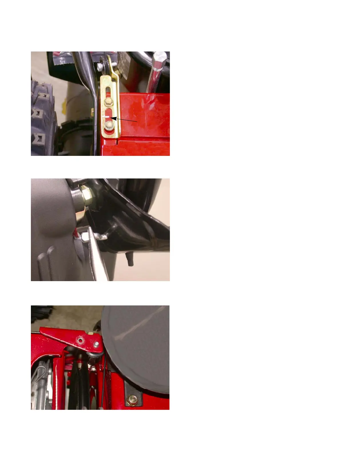
1. Place an alignment mark on the adjustment bracket
and the frame. See Figure 2.10.
2. Loosen the hex screws securing the adjustment
bracket to release tension off of the cable.
3. Detach the cable from the control handles. See Fig-
ure 2.11.
NOTE: On units with threaded Z-fittings:
• Loosen the jam nut.
• Unthread the cable from the Z-fitting.
4. Loosen the cable guide pulley on the adjustment
bracket and slip the cable out of the pulley groove.
5. Remove the belt cover.
6. Loosen the second cable guide pulley and slip the
cable out of the pulley groove. See Figure 2.12.
Figure 2.10
Alignment mark

 Loading...