GENERATOR SERVICE AND TROUBLESHOOTING MANUAL — REV. #0 (08/29/23) — PAGE 55
ECU 9988N
SINGLE OR MULTIPLE ENGINE CRANKS
(DIP SWITCH 4)
Using a small, at-blade screwdriver, set DIP switch 4
(Figure 56D) for either single or multiple engine cranks
as referenced in Table 4.
When DIP switch 4 is placed in the ON position (up) all the
multiple engine cranks will add together to create one large
engine crank. In effect it disables all other remaining cycles.
Placing DIP switch 4 in the OFF position will allow multiple
engine cranks as referenced in Table 3.
TESTING ENGINE OVERSPEED (DIP SWITCH 5)
After the engine has started and is running at normal speed,
using a small, at-blade screwdriver, place DIP switch 5 as
referenced in Figure 56D and Table 5 in the ON position
(up). If the overspeed potentiometer has been adjusted
correctly, the engine will shut down when an overspeed
fault occurs. For normal operation be sure DIP switch 5 is
placed in the OFF (down) position.
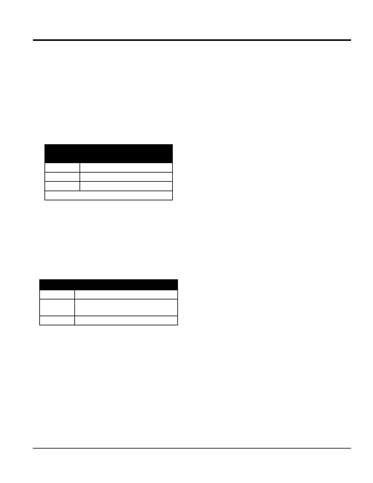
Table 4. Single/Multiple Engine Crank DIP
Switch Setting
SW4
1
FUNCTION
ON Single Engine Crank
OFF Multiple Engine Cranks
1
Factory built DCA units have Dip Switch 4 set to OFF.
Table 5. Overspeed DIP Switch Setting
SW5 FUNCTION
ON
Makes ECU think engine is going approximately
13% faster than it really is.
OFF True engine speed (normal operation)