GENERATOR SERVICE AND TROUBLESHOOTING MANUAL — REV. #0 (08/29/23) — PAGE 61
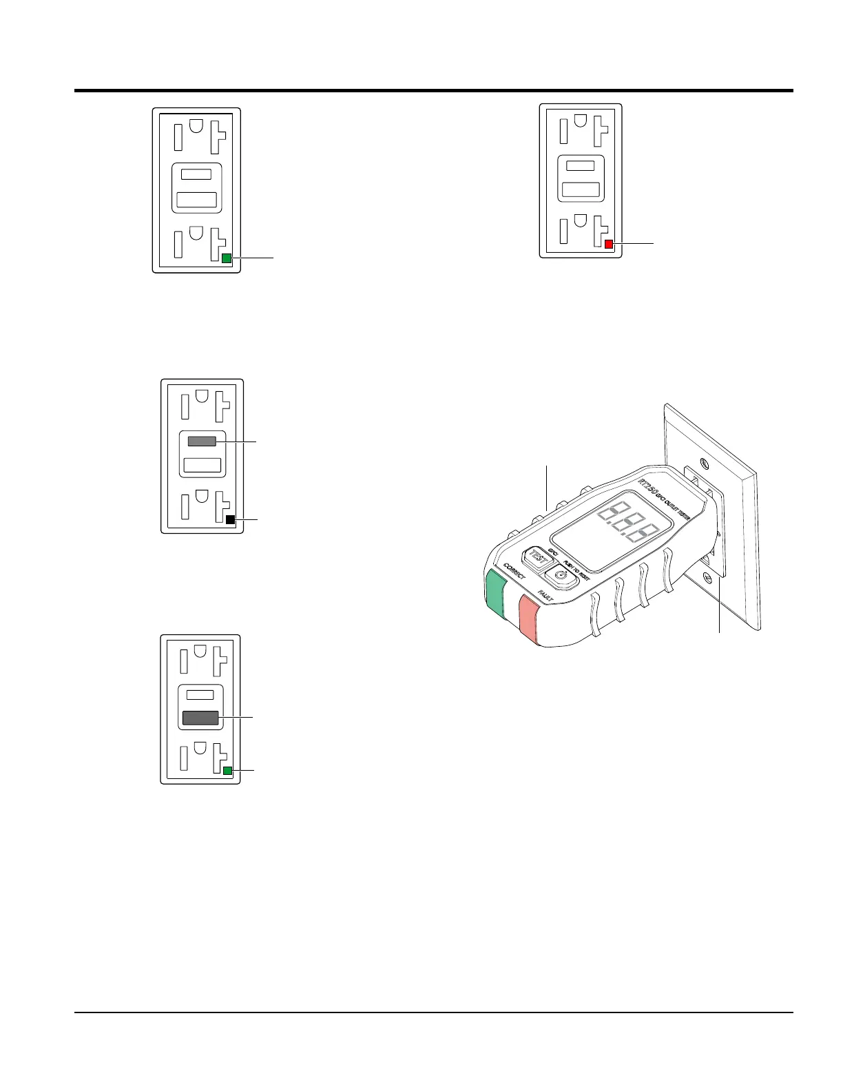
Figure 64. GFCI Receptacle (ON)
4. Press the TEST button (Figure 65) on the GFCI
receptacle and verify that the status LED turns OFF.
Figure 65. GFCI Receptacle (OFF)
5. Press the RESET button (Figure 66) to restore power
to the GFCI receptacle and verify that the status LED
is ON (GREEN).
Figure 66. GFCI Receptacle (ON/Restore)
6. If the status LED (Figure 67) is flashing (RED),
DO NOT use the GFCI receptacle and replace it
immediately.
GREEN
STATUS
LED ()ON
TEST
BUTTON
STATUS
LED (OFF)
RESET
BUTTON
GREEN
STATUS
LED (ON)
GROUND FAULT CIRCUIT INTERRUPTER
(
GFCI
)
Figure 67. GFCI Receptacle (RED Flashing LED)
GFCI Method 2 Testing
To measure the trip current of a GFCI requires a GFCI
tester (Figure 68). Insert the GFCI tester into the GFCI
receptacle.
Figure 68. GFCI Tester
The tester will determine if the GFCI is working correctly.
The GFCI will “sense” the difference in the amount of
electricity owing into the circuit to that owing out. This
trip value is typically four to six milliamps.
The GFCI reacts quickly (less than one-tenth of a second)
to trip or shut off the circuit.
One test that should not be performed on GFCI is a
high-load test. The GFCI contains small electronic parts
that are damaged if high voltages are applied to them. DO
NOT test any GFCI on a HI-POT, dialectic, or Doyle-type
tester.
RED
STATUS LED
FLASHING
GFCI TESTER
GFCI