GENERATOR SERVICE AND TROUBLESHOOTING MANUAL — REV. #0 (08/29/23) — PAGE 65
ENGINE STARTER
(
CRANK
)
RELAY CON'T
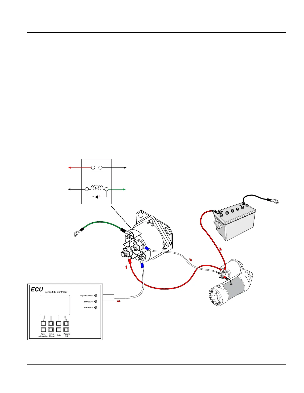
ENGINE START (CRANK) RELAY
For use on DCA70, 150, 180, 220 and 300 generators
(John Deere Engines). See previous page for other model
genrators.
As shown in Figure 71, a typical starter solenoid has one
small terminal for the starter control wire and two large
terminals for the positive battery cable and the thick wire
that provides power to the starter motor. The B+ battery
terminal connects the solenoid directly to the positive
battery cable.
The B+ battery voltage is also connected to the normally
open contact on the starter relay (terminal 4). When the
starter relay is energized at terminal 2 (coil) by the ECU
crank output signal (pin 5), this will cause the normally
open contacts (terminals 1 and 4) to close and the voltage is
sent via terminal 1 of the starter relay to the starter solenoid
(crank signal “S”). Terminal 3 on the starter relay is always
connected to chassis ground.
Figure 71. 4-Terminal Round Starter (Crank) Relay
(I)
4
3
2
1
(s)
s
B+
PIN 5
OUTPUT
SIGNAL
TO CHASSIS
GND
TO CHASSIS
GND
POS.
NEG.
BLK.
RED
WHT.
WHT.
GRN.
STARTER (CRANK)
RELAY
BATTERY
STARTER
SOLENOID
STARTER
COIL
3
ANODECATHODE
STARTER (CRANK) RELAY
DCA70, 150, 180, 220 and 300
TYPE GENERATORS
4
1
RED WHT.
NO
TO
CHASSIS GND.
TO
STARTER
SOLENOID
GRN.
2
TO ECU 845
PIN 5
WHT.
TO
STARTER
SOLENOID B+