GENERATOR SERVICE AND TROUBLESHOOTING MANUAL — REV. #0 (08/29/23) — PAGE 89
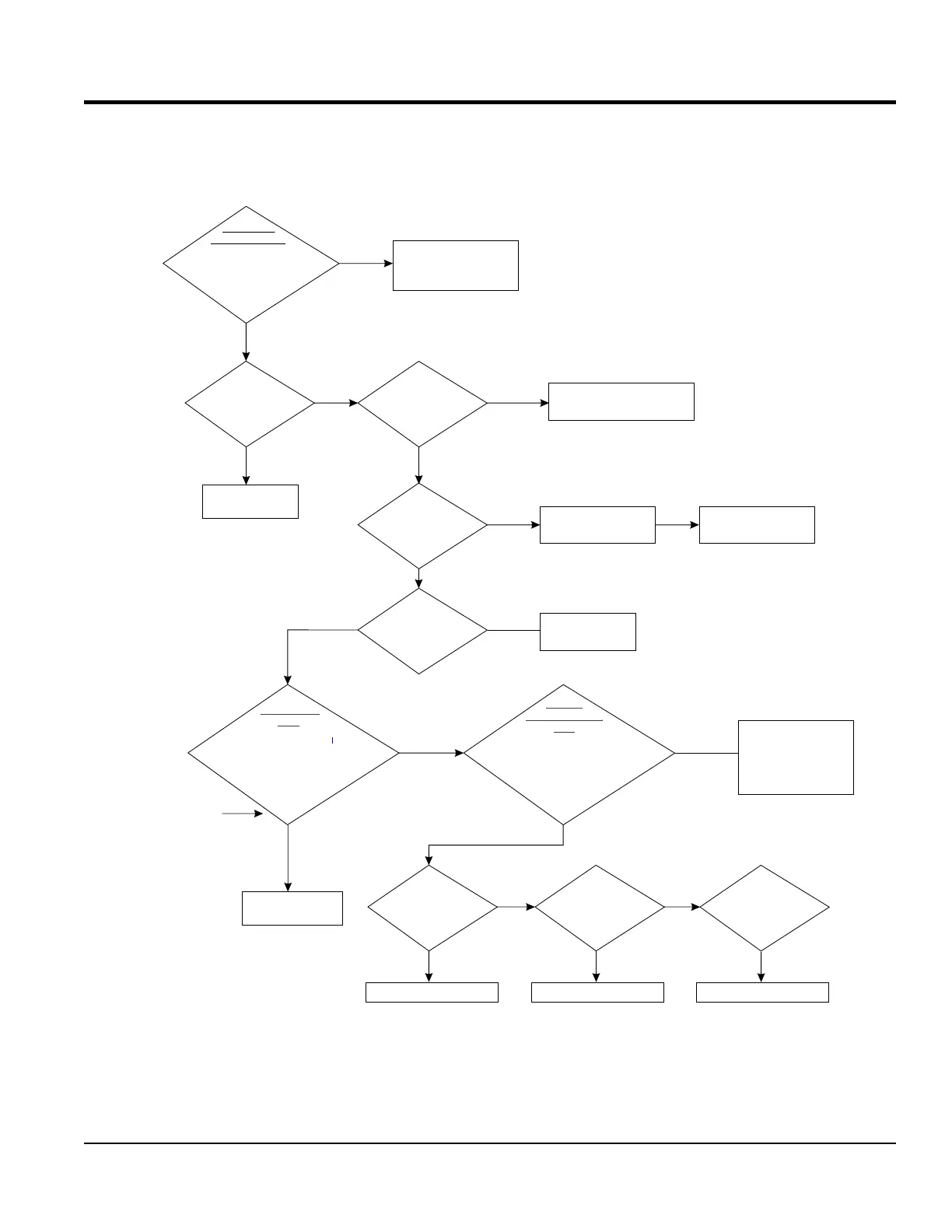
TROUBLESHOOTING FLOWCHARTS
Adjust or repair
engine.
Is voltage
balanced phase
to phase and
phase to
neutral
Does voltage
adjust with
rheostat?
Loose, damaged
or corroded
connectors
on AVR?
Repair or replace
faulty connectors
and retest unit.
Disconnect 6 pin connector
from CN1 receptacle on AVR.
Measure resistance at pins
Test Exciter
Field.
Reference Table 6
J and K on CN5 plug.
for correct
resistance
FAIL
Adjust the coarse
potentiometer
on AVR.
Test Rotating
Rectifier. Reference
Rotating Rectifier
test section.
Replace rotating rectifier.
With Rotating
Rectifier disconnected
test Exciter
Armature
FAIL
PASS
With Rotating
Rectifier disconnected
test Main
Field
Replace or refurbish rotor
Is engine
speed running
at 1800 rpm?
Voltage adjusts
but is not high enough
Verify Low
Voltage Output
Neutral
Replace or refurbish rotor
Resistance tolerance
is ± 2 ohms.
PASS
Start unit and run at
1800 RPM. Verify output voltage
at top of circuit breaker with
multimeter. Phase to Phase
and Phase to
FAIL
Inspect and troubleshoot
voltmeter on control
panel/digital controller
LOW VOLTAGE - WITH LOAD
NO
YES NO
YES
NO
NO
YES
Repair wiring or
replace Exciter Field
Manual
Excitation Field
Test
Disconnect 6 pin connector
fr AVom CN1 receptacle on R.
Connect 12 VDC battery to pins
J and K on CN5 plug
Reference Table 7
for correct
voltage
FAIL
PASS
If AC output voltage
meets values as
referenced in Table 7
Indicates faulty AVR,
Replace AVR and
retest unit.
PASS
FAIL
PASS
FAIL
YES
Reference troubleshooting
voltage unbalanced flowchart.