PAGE 90 — GENERATOR SERVICE AND TROUBLESHOOTING MANUAL — REV. #0 (08/29/23)
TROUBLESHOOTING FLOWCHARTS
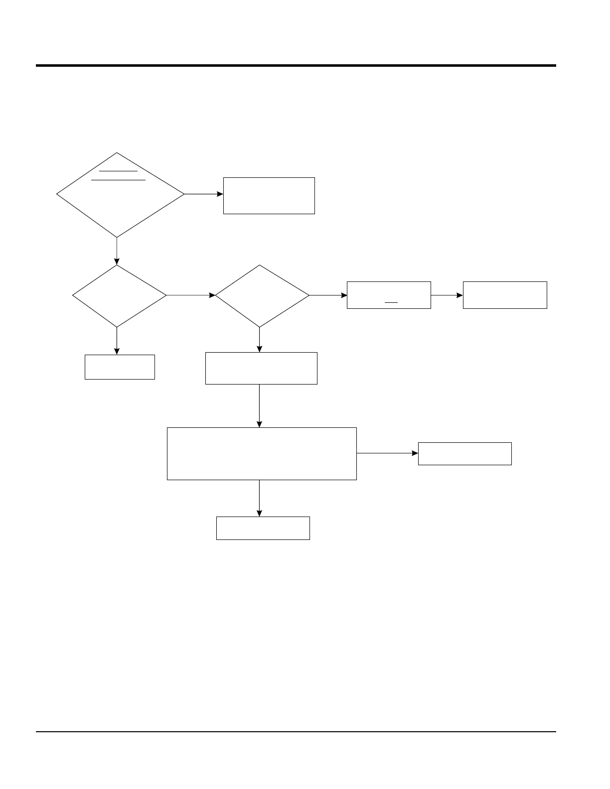
Adjust or repair
engine.
Does voltage
adjust with
rheostat?
Adjust the coarse
potentiometer
on AVR.
Is engine
speed running
at 1800 rpm?
Voltage adjusts
but is not low enough
Verify Low
Voltage Output
Neutral
Check 3-pin connector on AVR
(internal sensing leads) for
good connection.
240V Three-Phase Sensing
At 3-pin connector on AVR, back probe sensing leads
with multimeter. Test voltage phase to phase. Low
voltage or no voltage will cause AVR to compensate
by increasing the output to the Exciter Field.
Faulty AVR. Replace AVR.
Troubleshoot sensing
circuit wiring to AVR.
PASS
Start unit and run at
1800 RPM. Verify output voltage
at top of circuit breaker with
multimeter. Phase to Phase
and Phase to
FAIL
Inspect and troubleshoot
voltmeter on control
panel/digital controller
HIGH VOLTAGE
NO
YES
YES
NO
YES
NO