Video Grabber DGR-1000 User Manual - v. 1.4 (FW 1.9)
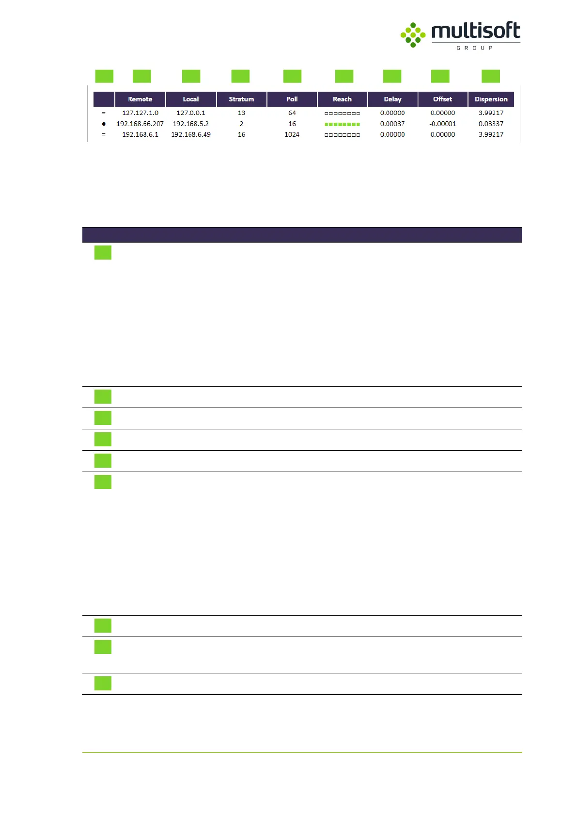
Figure 21: NTP status table on the Status page
The table mentioned above is a printout of standard NTP query program ntpdc with some styling to
improve the usability. It lists all NTP peers that are configured on the Video Grabber device along with
their basic parameters and state. See the description of the columns in the table below:
Single-character peer mode indicator. The list of possible modes is as
follows:
● – server has been chosen and is used as a clock reference
= – server is being polled in client mode
+ – server is in symmetric active mode
– – server is in symmetric passive mode
^ – server is broadcasting to this address
~ – server is sending broadcasts
IP address of the time source
IP address used to connect to the time source
Stratum number of the time source
Frequency (in seconds) at which the time source is polled for time
Indicates the success rate of last 8 polls:
□ – poll not performed
■ – poll successful
■ – poll failed
The newest polls are on the right while the oldest ones are on the left
e.g.:
■■■■■■■■ means that all 8 recent polls were successful
■■■■■■■■ means that from 8 recent polls 5
th
and 6
th
failed
Roundtrip time of the queries to the reference time (in seconds)
Difference between the reference time and the system clock (in
seconds)
Magnitude of jitter between several time queries (in seconds)
Table 10: Description of the parameters available in the NTP status table on the Status page