Video Grabber DGR-1000 User Manual - v. 1.4 (FW 1.9)
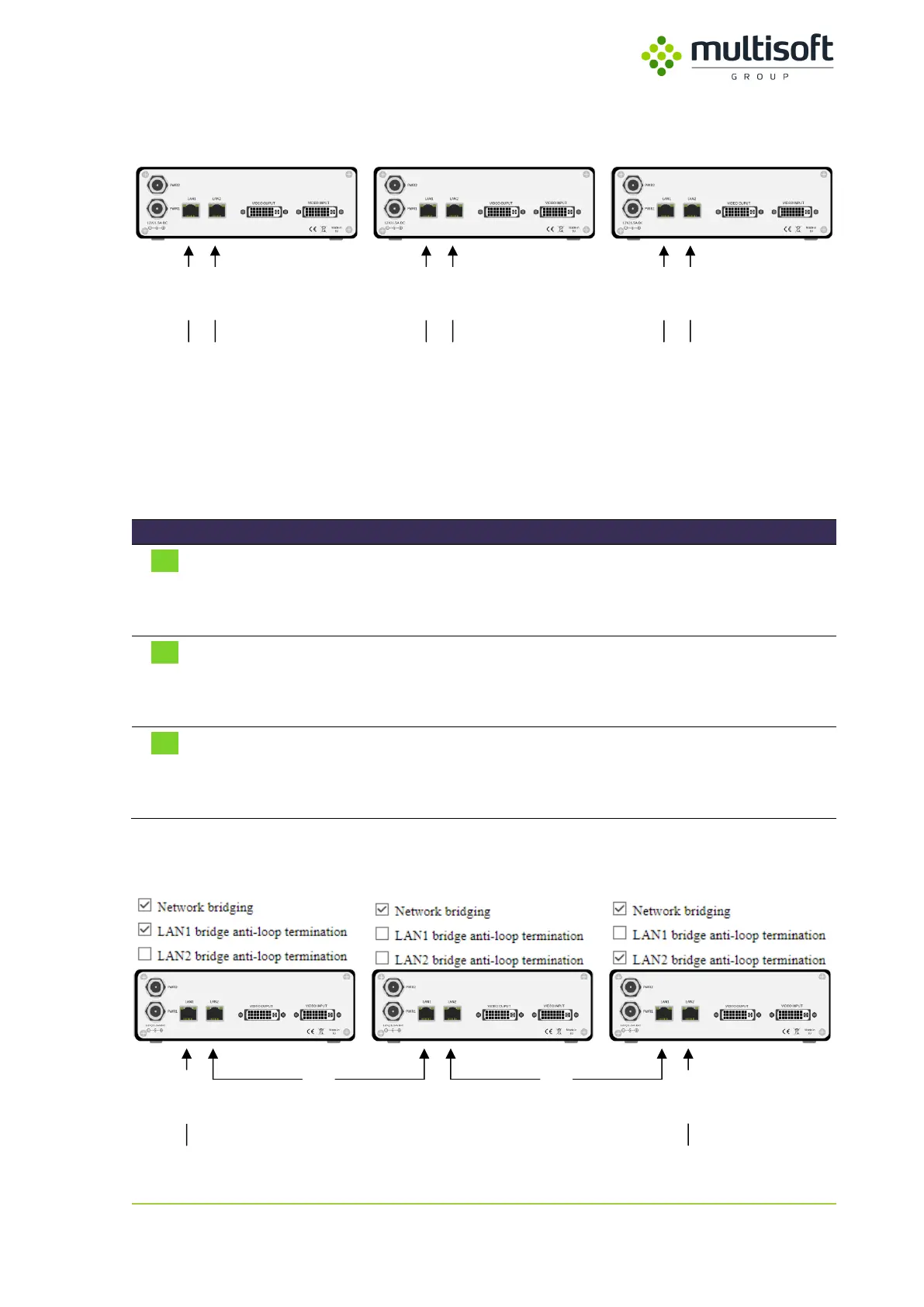
In typical setup each Video Grabber has its own, individual connection to the network (or networks in
case when both LAN ports are used).
Network B
Network A
Network B
Network A
Network B
Network A
Figure 25: Video Grabbers connected to networks A and B in a typical way
It is however possible to configure a couple of Video Grabbers to share their network interfaces so that
only two network connections would be needed to transmit the captured data from 3 or more devices.
This functionality is called ‘bridging’ and can be configured in the Bridging subsection of the network
section using the parameters described in the table below (check Figure 24 for parameter locations):
Enables the network bridging functionality:
checked – network bridging enabled
unchecked – network bridging disabled
Anti-loop
termination
(for LAN 1)
Enables anti-loop termination on the LAN 1:
checked – anti-loop termination enabled on LAN 1
unchecked – anti-loop termination disabled on LAN 1
Anti-loop
termination
(for LAN 2)
Enables anti-loop termination on the LAN 2:
checked – anti-loop termination enabled on LAN 2
unchecked – anti-loop termination disabled on LAN 2
Table 14: Description of parameters related to Network Bridging
For effective bridging one would have to configure connected Video Grabbers in the following way:
Network B
Network A
bridge bridge
Figure 26: Video Grabbers connected to networks A and B using network bridging