10 of 43
GT20 Wire and Programming Manual www.NabcoEntrances.com
P/N C-00140 Rev 5-7-18
CHAPTER 7: WIRING
Shut the installaon site, branch Circuit Breaker OFF Failure to do so may result in serious
personal or fatal injury When uncertain whether power supply is disconnected, always verify
using a voltmeter
All high voltage electrical connecons must be made by licensed electricians according to
Naonal and Local electrical codes/regulaons
Permanent wiring shall be employed as required by local codes
Keep sufcient spacing between high-voltage and low-voltage wiring. 120 VAC Power
wires must be routed (separate from other wiring) located near the top of inside Header
Ensure that incoming electrical ground is properly secured to the grounding screw or
grounding wire, whichever is provided
Aenon: Insert all Incoming 120 VAC Power wires into the pre drilled Electric Service Access Hole located at
the le or right side of Header End Cap
Aenon: Electrical circuit to Nabco operator must not be not shared with other equipment such as lighng,
cash registers, or any device that might cause electrical interference on the circuit
Note: It is recommended for the Installer to house all Incoming 120 VAC wires within an Electrical Conduit.
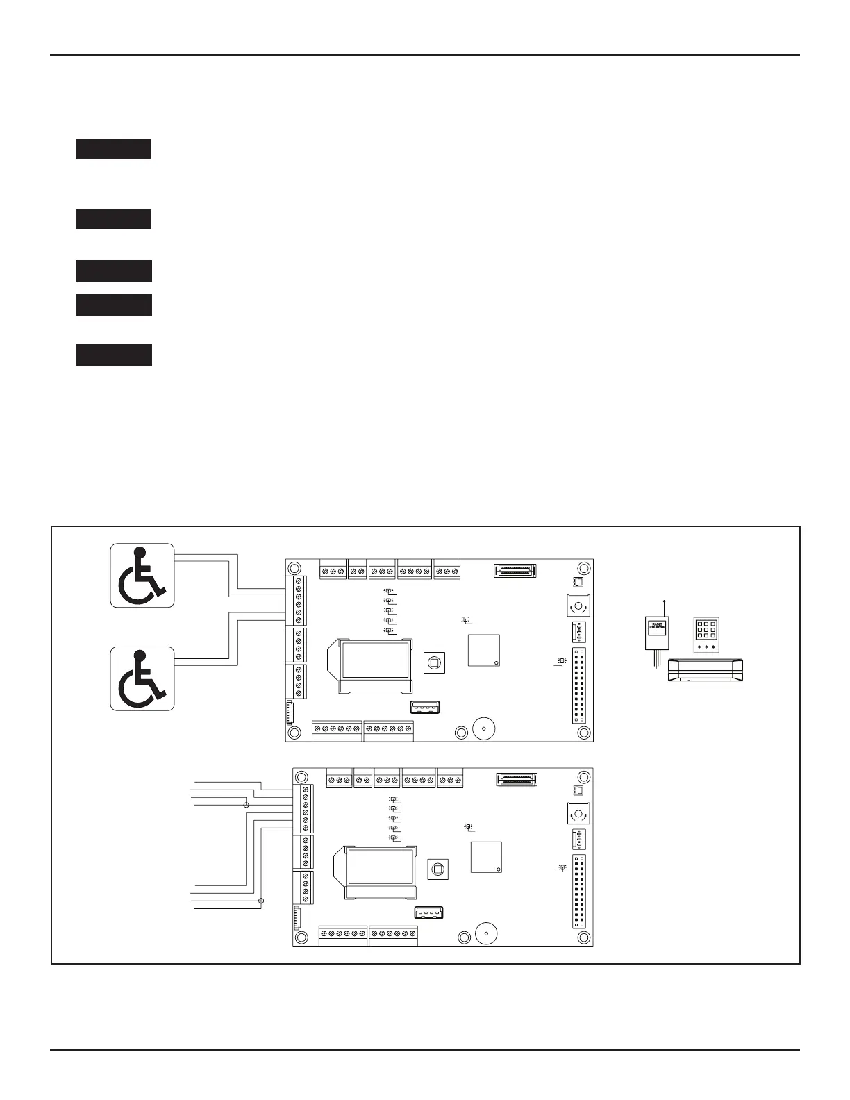
SECTION 71: Acvaon Devices
DN 1261
Power Ac va on Devices:
Sensors, Card Readers,etc...
All Devices Must Be
N.O. Dry Contact
NONPOWERED ACTIVATION DEVICES
POWERED ACTIVATION DEVICES
Exterior Push Plate
Interior Push Plate
RADIO
RECEIVER
!!!WARNING!!!
Total Power Consump on
of ALL Sensors and Powered
Ac va on Devices
MUST NOT Exceed 1.2 Amps
Exterior
Ac va on
Device
Interior
Ac va on
Device
SA SL SO SM SW
X110 X108
27 28 29 30 31
18 19 20 21
X107
14 15 16 17
X105
10 11 12 13
8 9
X101
X112 X104 X102
X118
X103
X113
R552
X109
U501
S501
X114
X116
30V OK
OE active (Opening element)
System OK
SE active (Safety element)
green
blue
yellow
5V OK
max.m in.
32
green
green
PGPOPIPU
CG CHCL
X117
SG
X111
BG BUBD
ERROR
E-Lock Relay
red
white
8
9
10
11
12
13
COM
N.O.
PWR+
PWR-
COM
N.O.
PWR+
PWR-
SA SL SO SM SW
X110 X108
27 28 29 30 31
18 19 20 21
X107
14 15 16 17
X105
10 11 12 13
8
9
X101
X112
2
X104 X102
X118
X103
X113
R552
X109
U501
S501
X114
X116
30V OK
OE active (Opening element)
System OK
SE active (Safety element)
green
blue
yellow
5V OK
max. min.
32
green
green
PGPOPIPU
CG CHCL
X117
SG
X111
BG BUBD
ERROR
E-Lock Relay
red
white
COM
N.O.
10
9
13
12
COM
N.O.
54
3
1
2
54
31
 Loading...