36 of 43
GT20 Wire and Programming Manual www.NabcoEntrances.com
P/N C-00140 Rev 5-7-18
Do not place nger or uninsulated tools inside the electrical GT20 Control Touching wires or
other parts inside the enclosure may cause electrical shock, serious injury or death
1. Ensure the Power is OFF.
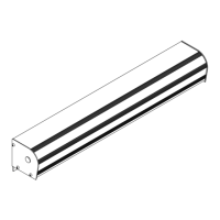
2. Use a T-10 Torx Allen Wrench to remove (4) M3 x 5 Torx Screws used to secure the GT20 Control Board. Set Aside. Figure 4.
a. The (4) Torx screws are located at (2) corners on the opposite side of the Terminal Strips and (2) middle locaon on the
opposite side of the Relay PCB Board Connector Strip.
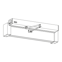
3. Insert (4) M3 x 12 Stand O Torx Screws within each screw hole.
4. Secure the Relay PCB Board onto the GT20 Control with (4) M3 x 5 Torx Screws.
5. Proceed to wire each PCB Terminal accordingly.
SECTION 112: Program the Relay PCB Board
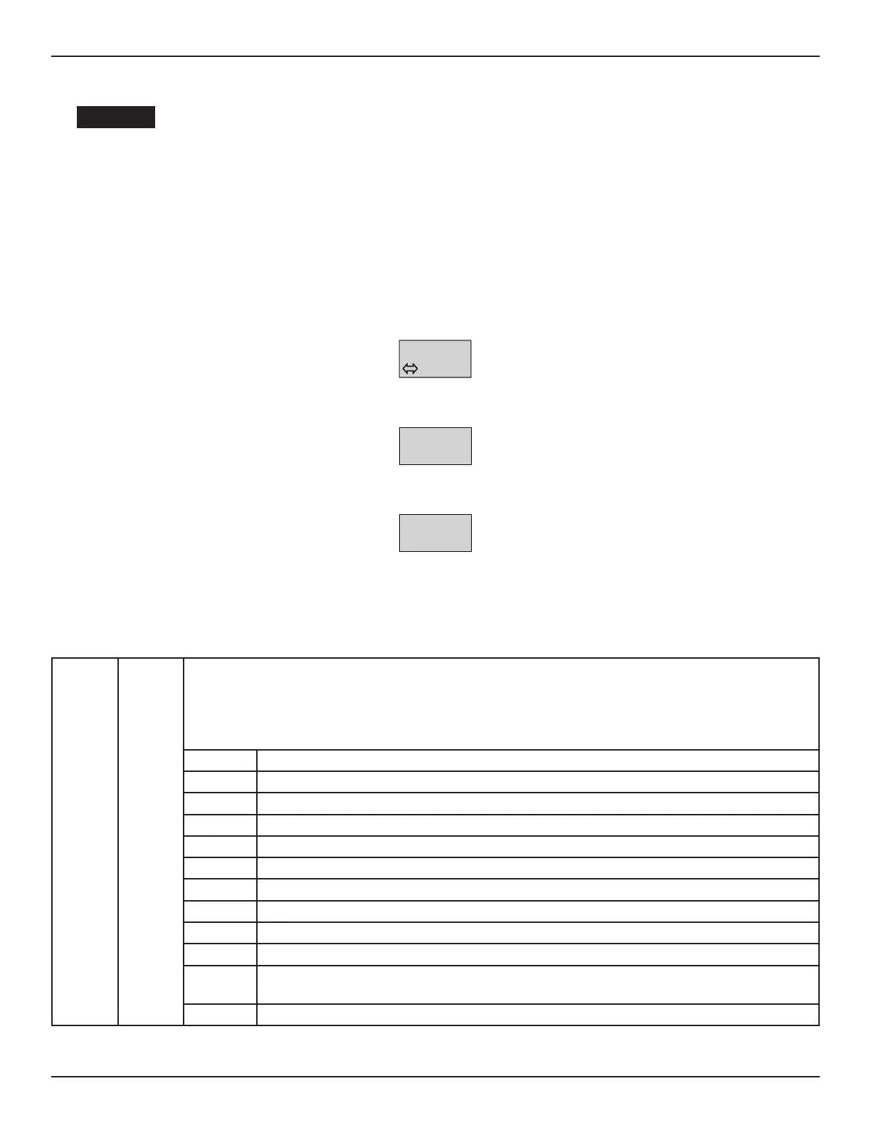
1. Switch-on the Main Power Switch. The Home Page will be displayed.
>##<
E01
2. Briey push down on the Joysck. The Menu Selecon Page will be displayed.
3. Move the Joysck to the Right or Le unl the Menu CONFIG is displayed.
CONFIG
4. Briey push down on the Joysck. An Element Page will be displayed.
5. Move the Joysck Down unl the Element RC 0.1 is displayed.
RC 0.1
CLOSED
6. Briey push down on the Joysck. The Value will start to blink on the lower half of the screen.
7. Move the Joysck to the Right or to the Le to select(1) the appropriate Value.
8. Repeat steps 5 thru 7 unl all Relay PCBs are programmed within the GT20 Control.
1123 Conguraon Menu for Relay PCB Board
RC 0.1
RC 0.2
RC 0.3
RC 0.4
CLOSED
OPEN
ERROR
GONG
Only (1) PCB Terminal per Switch Acvaon is allowed. For example (2) acvaons (during closing and
opening) must be wired to (2) dierent PCB Terminals.
CLOSED Relay switches when the Door Panel is fully closed.
OPENNG Relay switches when the Door Panel is opening.
OPEN Relay switches when the Door Panel is fully open.
CLOSING Relay switches when the Door Panel is closing.
ERROR Relay switches if the GT20 Control detects an Error(s).
PSAUTO Relay switches when the Program Selector is in Mode: AUTOMATIC
PSNIGHT Relay switches when the Program Selector is in Mode: NIGHT
PSEXIT Relay switches when the Program Selector is in Mode: EXIT
PSOPEN Relay switches when the Program Selector is in Mode: OPEN
PSMANU Relay switches when the Program Selector is in Mode: MANUAL
GONG Relay switches momentarily during the me the GT20 Control recieves a signal from: Terminal
12 and Terminal 13 (Opening Command Inside).
LOCKED Relay switches during the me the Door Panel is LOCKED with an electric lock.
 Loading...