37 of 43
www.NabcoEntrances.com GT20 Wire and Programming Manual
Rev 5-7-18 P/N C-00140
1. Go back to the Menu Page:
2. Move the Joysck to the Right or Le unl the Menu DIAGNOSTICS is displayed.
DIAGNO-
STICS
3. Briey push down on the Joysck. The Element Page will be displayed.
4. Move the Joysck to the Right or Le unl the Element RO+ R1- FP- RP- is displayed.
5. Briey push down on the Joysck. The Value will start to blink on the lower half of the screen.
6. Move the Joysck to the Right or to the Le to select(1) the appropriate Value.
7. Repeat steps 3 thru 6 unl all Relay PCBs are programmed within the GT20 Control.
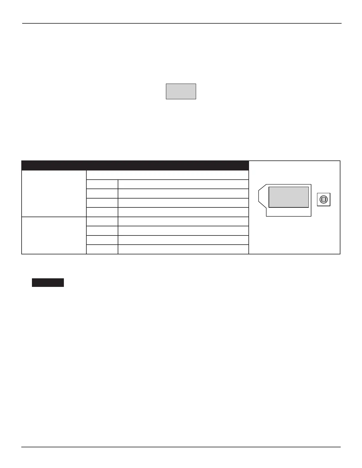
1124 The Diagnosc Menu for Relay PCB Board
Diagnostic Element Address Description
Joystick
Display
R0+R1-
FP-RP-
Only (1) Relay PCB Board (R0) has
been installed
Displays what the Door Panel is doing
RO Address for Relay Board (RC 0)
R1 N/A
FP N/A
RP N/A
+ Idened and ready for operaon
- Neither idened nor registered
e Defecve or Error
x Removed
CHAPTER 12: TROUBLESHOOTING
Electrocuon hazard! Before working on any live elements, disconnect 120 VAC from unit
If a malfuncon occurs, which might be detrimental to the safety of users, and cannot
immediately be repaired The owner must be informed The installaon shall be taken out of
operaon and must be repaired as soon as possible
Note: Every troubleshoong procedure which is carried out must be entered into the control booklet. Never leave an unsafe
door operaonal. If the door is not immediately repairable, turn o equipment. Advise the owner that the door should
not be used unl repairs are made
SECTION 121: Malfuncon with Error - No
Note: Error is indicated on the display of the Control Unit.
X
X
X
X
X
 Loading...