35 of 43
www.NabcoEntrances.com GT20 Wire and Programming Manual
Rev 5-7-18 P/N C-00140
SECTION 1010: Check Connecons
Note: A small white (m) and a small white (s) indicates: a missing connecon.
Note: Both Operator Assemblies must be running o the same power circuit.
Note: Parameters: ILAuto, ILExit and ILNigt enable yo to congure the operang modes in which the Interlock system shall
be acve.
1. Check the LCD Display on the Master GT20 Control to see if a small black (w) is visible on the rst level (connecon exisng).
2. Transmit a Key (open) command to the exterior control (A) by applying a jumper to terminals 2 & 3:
X The LCD will display a big black (W) (door is not closed).
X While the Exterior door (A) is open, transmit a Key command to the Control for the Interior door (B). The Interior door
must not be able to open.
3. Transmit a Key command to the Interior Control (B):
X On the Control display, a big black (W) appears when the Interior door is open.
X While the interior door is Open (B), transmit a Key command to the Control of the Exterior door (A). The Exterior door
must not be able to open.
CHAPTER 11: RELAY PRINT
X
X
X
X
•
X
X
X
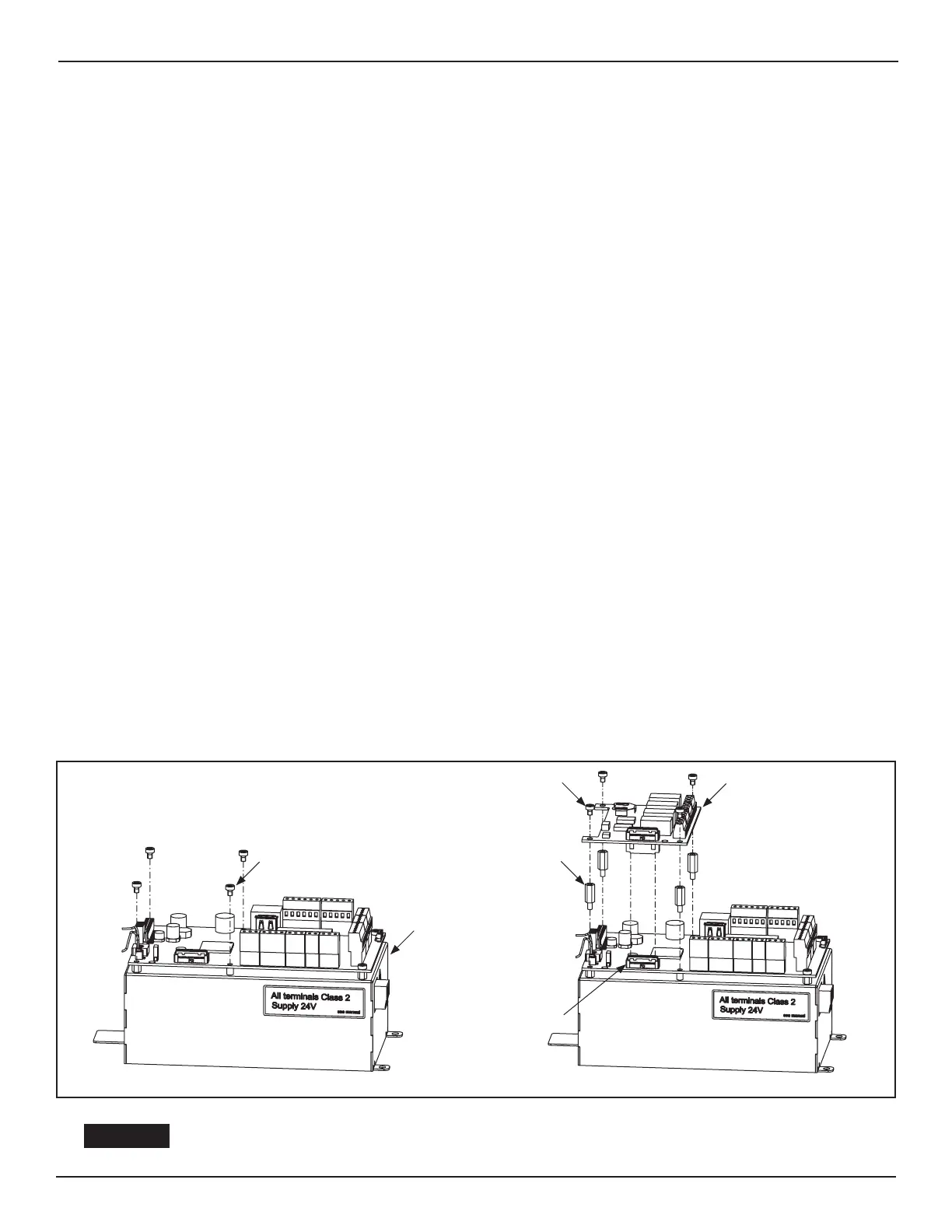
SECTION 111: Install the Relay PCB Board
DN 1264
Female Connector
GT20 Control
Relay PCB Board
(4x) M3 x 12 Stand
Off Torx Screw
(4x) M3 x 5 Torx Screw
M3 x 5 Torx Screw
Figure 7
Shut Breaker OFF Failure to do so may result in serious personal or fatal injury When
uncertain whether power supply is disconnected, always verify using a voltmeter
 Loading...