FPΣ
6.4 Pulse Output Function
6-25
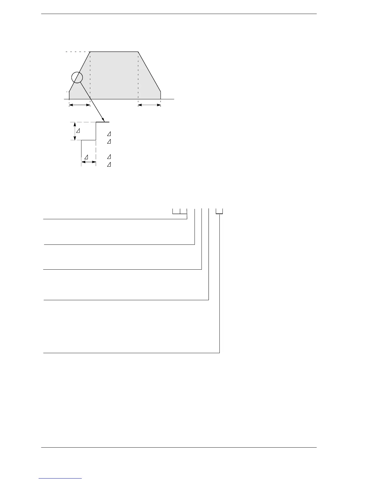
Pulse output diagram
300 ms 300 ms
5000 Hz
500 Hz
0Hz
10000 pulses
f
t
f = (5000 - 500) ÷ 30 steps = 150 Hz
With 30 steps:
t = 300 ms ÷ 30 steps = 10 ms
f = (5000 - 500) ÷ 60 steps = 75 Hz
With 60 steps
t = 300 ms ÷ 60 steps = 5 ms
Figure 92: FPΣ Pulse output diagram of “F171” instruction
Operation mode and output method
00: Incremental CW/CCW
02: Incremental PLS and SIGN (forward off / reverse on)
03: Incremental PLS and SIGN (forward on / reverse off)
10: Absolute CW/CCW
12: Absolute PLS and SIGN (forward off / reverse on)
13: Absolute PLS and SIGN (forward on / reverse off)
H jjjjjjjj
0: Fixed
Duty (on width)
0: Duty 1/2 (50%)
1: Duty 1/4 (25%)
Frequency range
0: 1.5 Hz to 9.8 kHz
1: 48 Hz to 100 kHz
2: 191 Hz to 100 kHz
(*1): Control code <H constant>
(*2): Frequency (Hz) “K constant”
1.5 Hz to 9.8 KHz [K1 to K9800 (units: Hz)] (Max. error near 9.8 kHz approximately -0.9 kHz)
* Set “K1” to specify 1.5 Hz.
48 Hz to 100 KHz [K48 to K100000 (units: Hz)] (Max. error near 100 kHz approximately -3 kHz)
191 Hz to 100 KHz [K191 to K100000 (units: Hz)] (Max. error near 100 kHz approximately -0.8 kHz
(*3): Acceleration/deceleration time (ms) “K constant”
With 30 steps: K30 to K32767
With 60 steps: K36 to K32767
(*4): Target value “K constant”
K-2147483648 to K2147483647
Number of acceleration/deceleration steps
0: 30 steps
1: 60 steps (Can be specified for only Ver. 2.0 or later.)
Figure 93: FPΣ Control code of “F171” instruction

 Loading...

