FPΣ 10.1 PLC Link
10 - 3
10.1 PLC Link
This section explains about the overview of PLC link function.
10.1.1 Overview of Function
What is the PLC Link?
The PLC link is an economic way of linking two PLCs, using a twisted-pair cable.
Data is shared between the PLCs using a link relay (L) and a link register (LD).
With a PLC link, the statuses of the link relays and link registers for one PLC are
automatically fed back to other PLCs on the same network.
ThePLClinkisnotsettobeusedinthedefaultsettings,sothesettingof systemregister
No. 412 should be changed to “PLC Link” in order to use the function.
Thevarious PLC unitsandlinkareas are allocated usingthe systemregisters. Formore
detailed information, please see page 10 - 5, “Communication Parameter Settings”.
No.1
No.3
No.2
No.1
No.3
No.2
No.1
No.3
No.2
RS485
Transmitted
area
Received
area
Received
area
Transmitted
area
Received
area
Received
area
Transmitted
area
Received
area
FPΣ
(Unit No. 1)
FPΣ
(Unit No. 2)
FPΣ
(Unit No. 3)
FPΣ
(Unit No. 4)
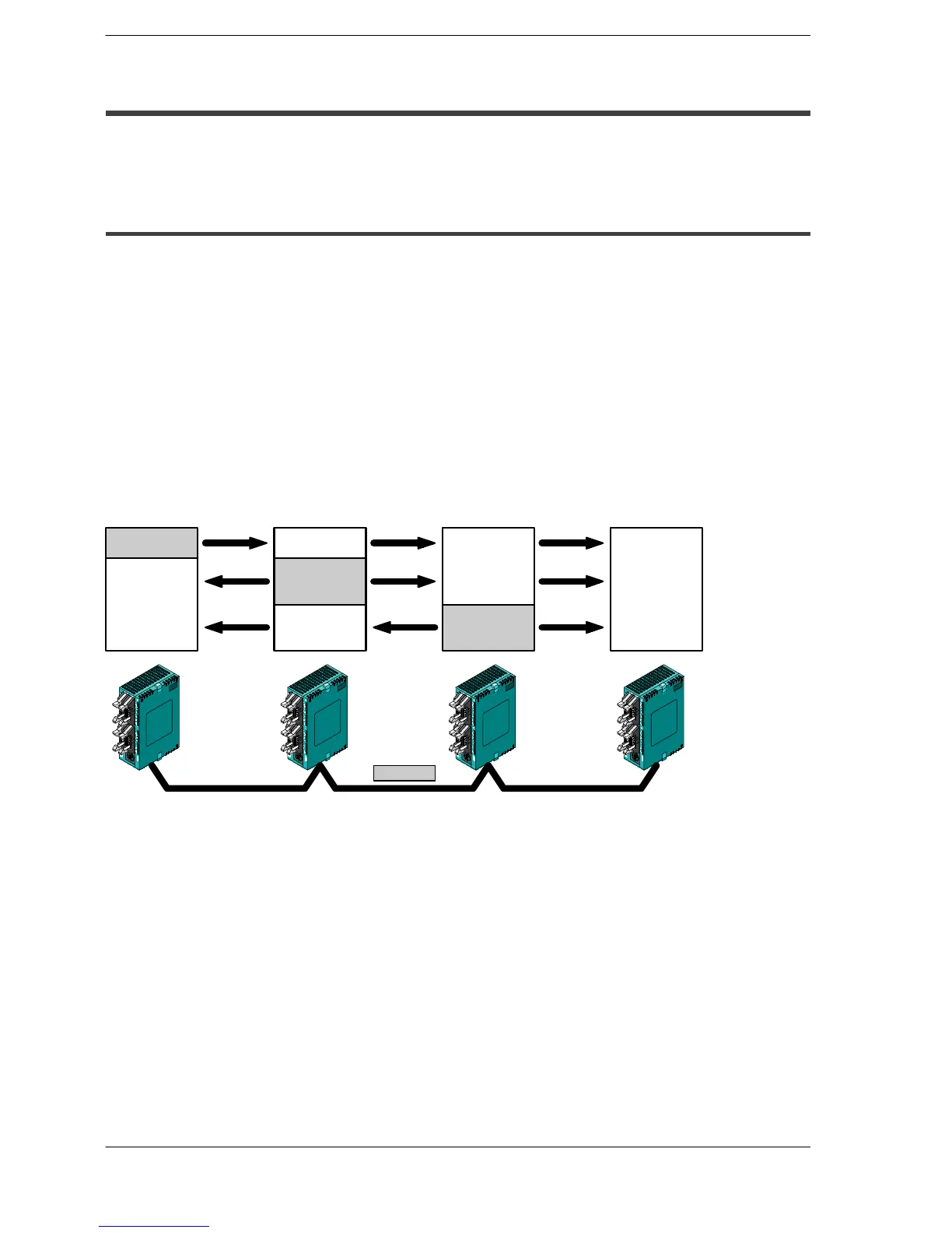
The link relays and link registers of the various PLCs contain areas where data is sent and areas
where data is received, and these are used to share data among the PLCs.
Figure 201: FPΣ PLC link function (overview)

 Loading...

