FPΣ
Communication Function 3 PLC Link Function
10 - 10
10.2.3 Allocation of Link Relay and Link Register
Link area allocation
The PLC link function is a function that involves all of the PLCs that have been booted
in the MEWNET-W0 mode.
To use the PLC link function, a link area needs to be allocated. Set the allocations for
both the link relays and link registers.
Link area allocations are specified using system registers.
System registers
No. Name Set value
No. 40 Range of link relay used for PLC link 0 to 64 words
No. 41 Range of link register used for PLC link 0 to 128 words
No. 42 Starting no. for link relay transmission 0to63
No. 43 Link relay transmission size 0 to 64 words
No. 44 Starting no. for link register transmission 0 to 127
No. 45 Link register transmission size 0 to 127 words
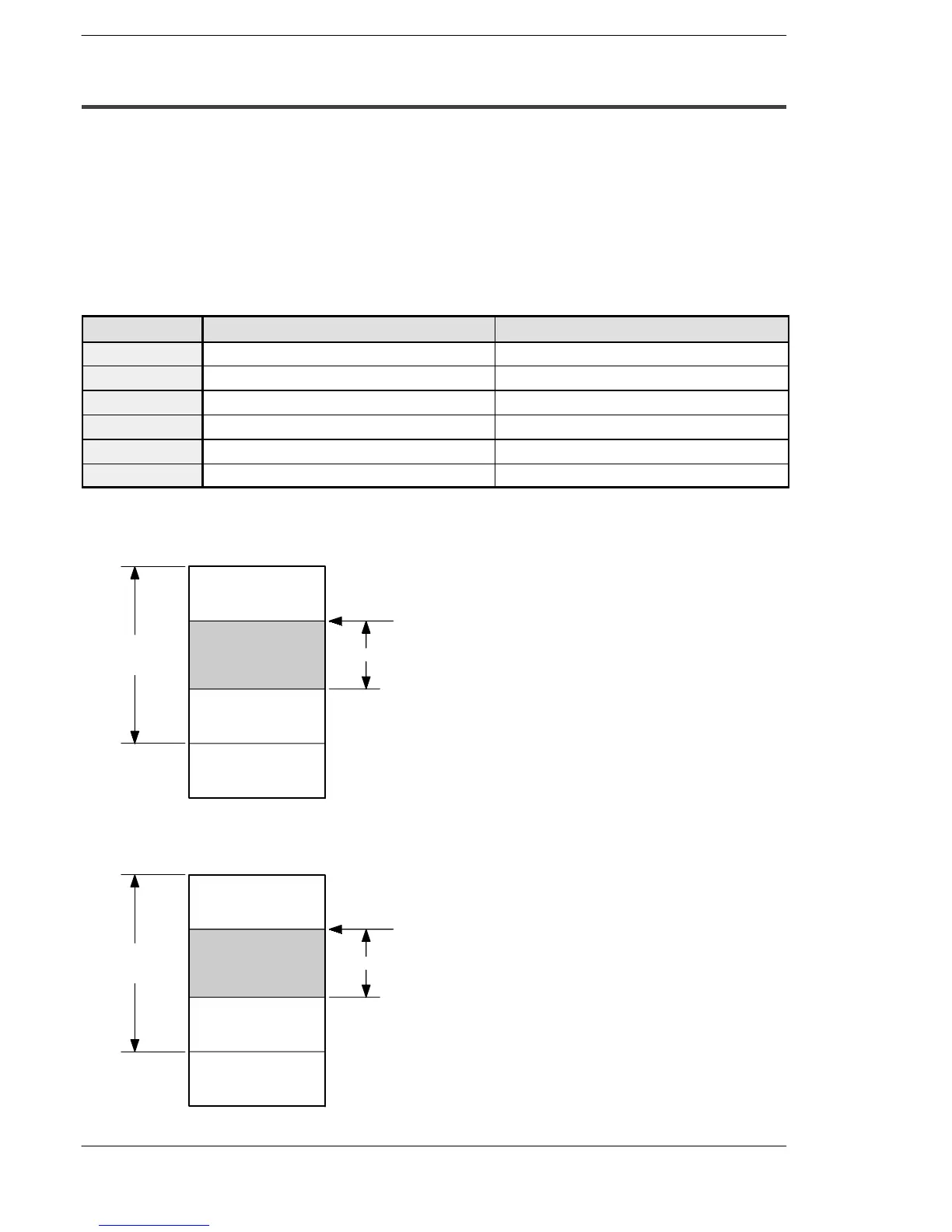
Relation of system register set value to link area
Link relay
Received area
Received area
Transmitted area
Not used area
for PLC link
No. 40
Range of link relay
used for PLC link
0
No. 43 Link relay transmission size
No. 42
Starting no. for link relay
transmission
Max. 64
(word)
Figure 207: FPΣ Link relay allocation
Link register
Received area
Received area
Transmitted area
Not used area
for PLC link
No. 41
Range of link
register used for
PLC link
No. 45 Link register transmission size
No. 44
Starting no. for link
register transmission
Max. 128
(word)
Figure 208: FPΣ Link register allocation

 Loading...

