FPΣ
6.4 Pulse Output Function
6-43
6.4.6 Sample Program for Positioning Control
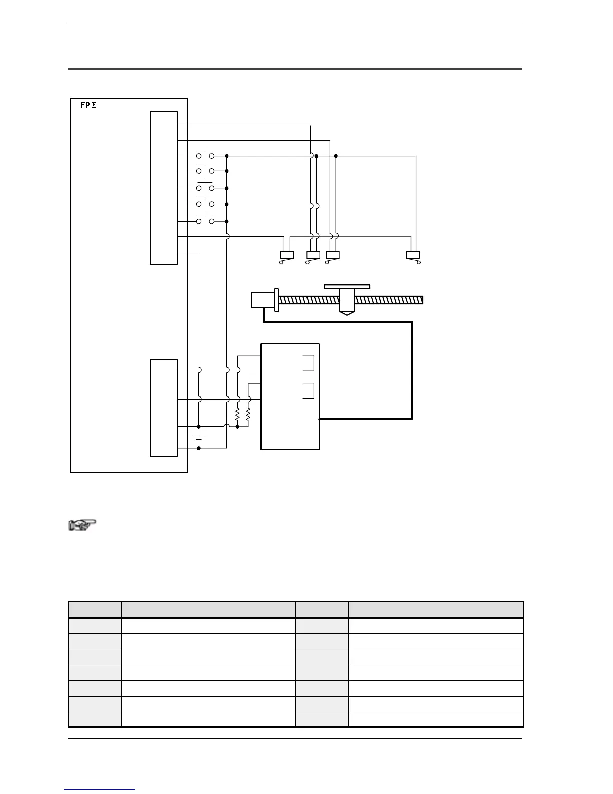
Wiring example
X2
X8
X9
XA
X3
XB
XC
XD
COM
Y0
Y1
+
–
Input terminal
Home sensor
Positioning start (+)
Home return start
Near home sensor
JOG start (+)
JOG start (-)
Overrun
Positioning start (-)
Output terminal
Pulse output CW
Pulse output CCW
COM
Power supply
Stepping motor driver
(Note)
CW input
COM
CCW input
Stepping motor
(- side)
(+ side)
Moving table
b contact
a contact
a contact
b contact
24 V
DC
Figure 105: FPΣ Pulse output function - sample program (wiring)
Note
When the stepping motor input is a 5 V optical coupler type,
connect a 2 kΩ 1/4 W resister.
Table of I/O allocation
I/O No. Description I/O No. Description
X2
Home sensor input
XD
Overrnning signal
X3
Near home sensor input
Y0
Pulse output CW
X8
Positioning start signal (+)
Y1
Pulse output CCW
X9
Positioning start signal (-)
R10
Positioning in progress
XA
Home return start signal
R11
Positioning operation start
XB
JOG start signal (+)
R12
Positioning done pulse
XC
JOG start signal (-)
R903A
High-speed counter control flag for CH0

 Loading...

