FPΣ
Specifications
13 - 16
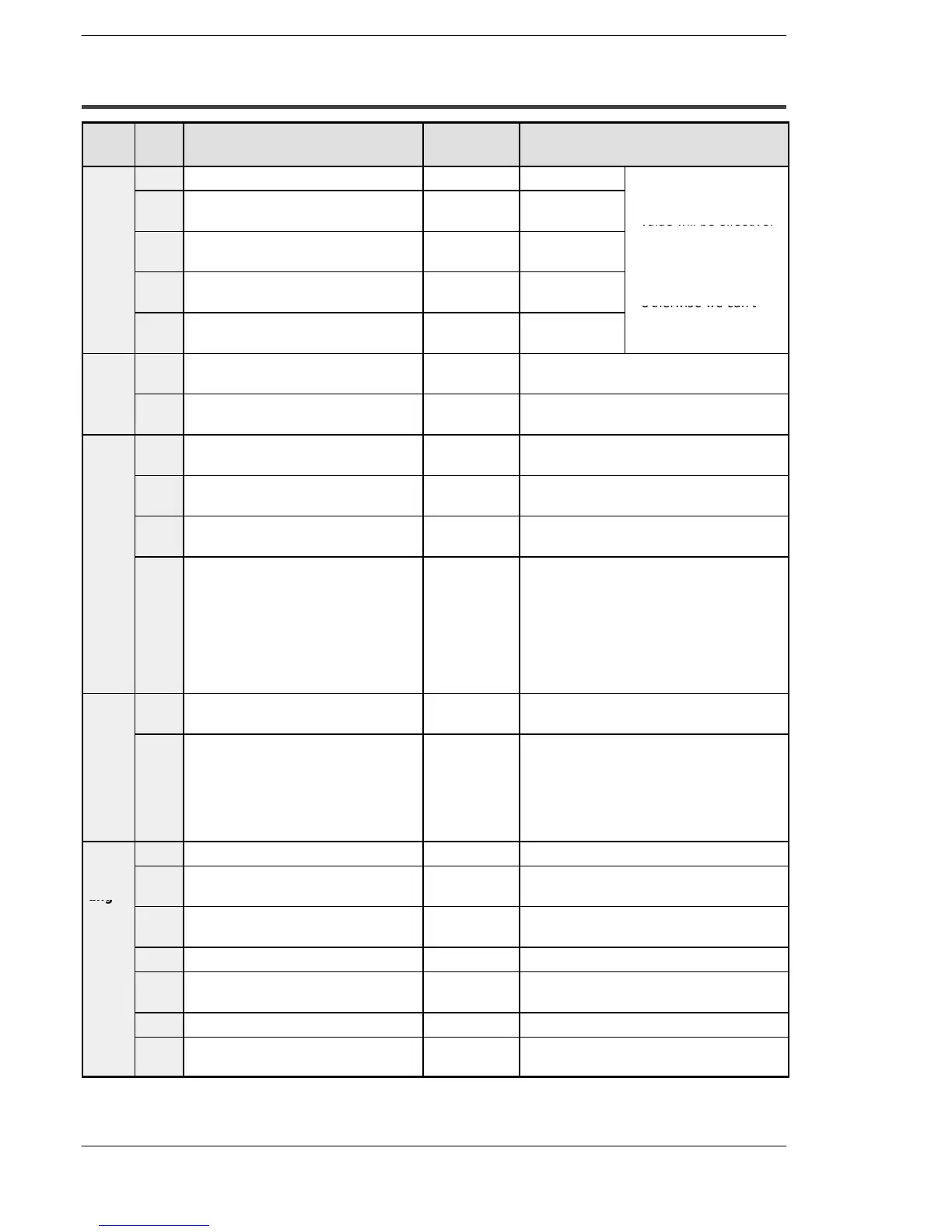
13.4.2 Table of System Registers
Item No. Name Default
value
Descriptions
Hold/
5 Starting number setting for counter 1008 0 to 1024
S In case of using
Non-
hold 1
6 Holdtype area starting number setting
for timer and counter
1008 0 to 1024
back-up battery
(option), the setting
value will be effective.
7 Holdtype area starting number setting
for internal relays
90 0to98
S In case of not using
back-up battery
8 Holdtype area starting number setting
for data registers
32710 0 to 32765
(option), please keep
the default value.
Otherwise we can’t
14 Hold or non-hold setting for step
ladder process
Non-hold Hold/Non-hold
guarantee the function
of hold/non-hold value.
Hold/
Non-
10 Hold type area starting number for
PLC link relays
64 0to64
hold 2
12 Hold type area starting number for
PLC link registers
128 0 to 128
Action
on
20 Disable or enable setting for dupli-
cated output
Disabled Disabled/Enabled
error
23 Operation setting when an I/O
verification error occurs
Stop Stop/Continuation of operation
26 Operation setting when an operation
error occurs
Stop Stop/Continuation of operation
4 Alarm Battery Error
(Operating setting when battery error
occurs)
Disabled Disabled: When a battery error occurs, a
self-diagnostic error is not is-
sued and the ERROR/ALARM
LED does not flash.
Enabled: When a battery error occurs, a
self-diagnostic error is issued
and the ERROR/ALARM LED
flashes.
Time
set-
31 Wait time setting for multi-frame com-
munication
6500.0 ms 10 to 81900 ms
ting
34 Constant value settings for scan time Normal scan 0: Normal scan
0 to 350 ms: Scans once each specified
time interval.
0: Normal scan
0 to 350 ms: Scans once each specified
time interval.
PLC
40 Range of link relays used for PLC link 0 0 to 64 words
link
set-
ting
41 Range of link data registers used for
PLC link
0 0 to 128 words
42 Starting number for link relay
transmission
0 0to63
43 Link relay transmission size 0 0 to 64 words
44 Starting number for link data register
transmission
0 0 to 127
45 Link data register transmission size 0 0 to 127 words
47 Maximum unit number setting for
MEWNET-W0 PLC link
16 1to16

 Loading...

