FPΣ
Specifications
13 - 44
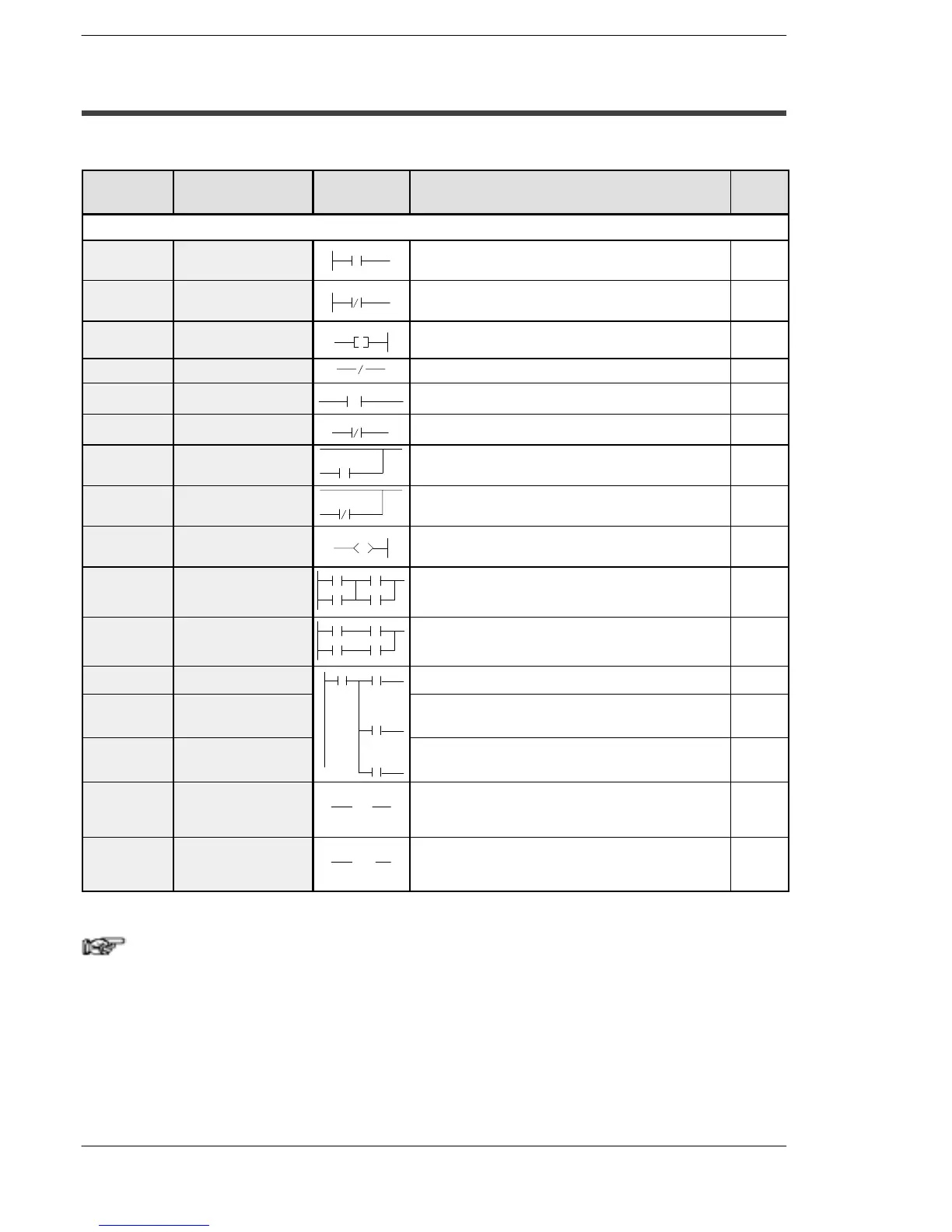
13.8 Table of Instructions
Table of Basic Instructions
Name Boolean Symbol Description Steps
(* Note)
Sequence basic instructions
Start ST
X,Y,R,L,T,C
Begins a logic operation with a Form A (normally
open) contact.
1 (2)
Start Not ST/
X,Y,R,L,T,C
Begins a logic operation with a Form B (normally
closed) contact.
1 (2)
Out OT
Y,R,L
Outputs the operated result to the specified output. 1
Not / Inverts the operated result up to this instruction. 1
AND AN
X,Y,R,L,T,C
Connects a Form A (normally open) contact serially. 1 (2)
AND Not AN/
X,Y,R,L,T,C
Connects a Form B (normally closed) contact serially . 1 (2)
OR OR
X,Y,R,L,T,C
Connects a Form A (normally open) contact in
parallel.
1 (2)
OR Not OR/
X,Y,R,L,T,C
Connects a Form B (normally closed) contact in
parallel.
1 (2)
Alternative
out
ALT
Y,R,L
A
Inverts the output condition (on/off) each time the
leading edge of the trigger is detected.
3
AND stack ANS Connects the multiple instruction blocks serially. 1
OR stack ORS Connects the multiple instruction blocks in parallel. 1
Push stack PSHS Stores the operated result up to this instruction. 1
Read stack RDS
Reads the operated result stored by the PSHS
instruction.
1
Pop stack POPS Reads and clears the operated result stored by the
PSHS instruction.
1
Leading
edge
differential
DF
(DF )
Turns on the contact for only one scan when the
leading edge of the trigger is detected.
1
Trailing
edge
differential
DF/
(DF/ )
Turns on the contact for only one scan when the
trailing edge of the trigger is detected.
1
Note
When T256/C256 or higher, R9000 or higher is used, the number
of steps is the number in parentheses.

 Loading...

