FPΣ
10.4 Connection Example of PLC Link
10 - 21
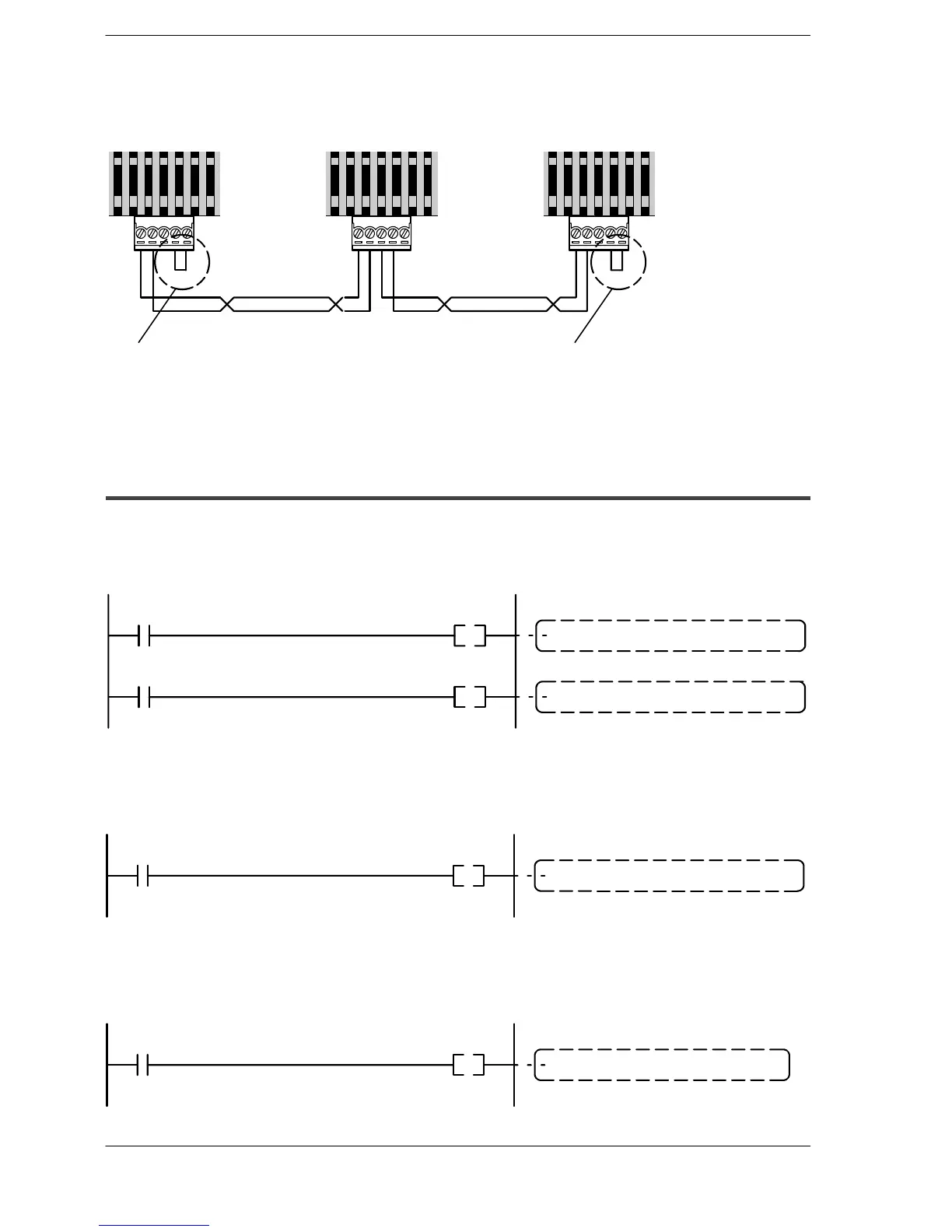
Connection diagram
FPΣ
(Unit No. 1)
FPΣ
(Unit No. 2)
FPΣ
(Unit No. 3)
Transmission line Transmission line
Thefinal unit(terminal station)should
be shorted between the transmission
line (–) and the E terminal.
The final unit (terminal station) should
be shorted between the transmission
line (–) and the E terminal.
Figure 219: FPΣ Connection diagram when using a PLC link with three FPΣ units
10.4.2 Sample Programs
Program of “unit No. 1” FPΣ contorl unit
When X1 is input, the L0 of the link relay goes on, and when X2 is input, the L1 of the
link relay goes on.
L0X1
L1
X2
“Unit No. 2” FPΣ control unit begins operation
“Unit No. 3” FPΣ control unit begins operation
Figure 220: Sample program - unit No. 1
Program of “unit No. 2” FPΣ contorl unit
When the L0 of the link relay goes on, Y0 is output.
Y0
L0
Y0: output
Figure 221: Sample program - unit No. 2
Program of “unit No. 3” FPΣ contorl unit
When the L1 of the link relay goes on, Y0 is output.
Y0
L1
Y0: output
Figure 222: Sample program - unit No. 3

 Loading...

