FPΣ
Communication Function 3 PLC Link Function
10 - 20
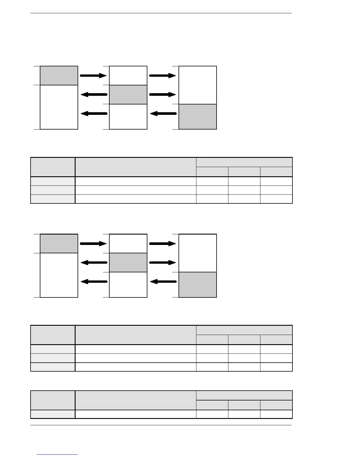
Allocation of link area
Link relay allocation
FPΣ
(Unit No. 1)
FPΣ
(Unit No. 2)
FPΣ
(Unit No. 3)
No.1
No.3
No.2
WL0
19
20
63
WL0
19
20
63
WL0
63
39
40
39
40
No.1
No.3
Transmitted
area
Receivedarea
Transmitted
area
Receivedarea
Receivedarea
Receivedarea
Transmitted
area
No.2
Figure 217: FPΣ Link relay allocation when using a PLC link with three FPΣ units
System register
No. Name Set value of various control unit
No. 1 No. 2 No. 3
No. 40
Range of link relay used for PLC link 64 64 64
No. 42
Starting no. for link relay transmission 0 20 40
No. 43
Link relay transmission size 20 20 24
Link register allocation
FPΣ
(Unit No. 1)
FPΣ
(Unit No. 2)
FPΣ
(Unit No. 3)
Transmitted
area
Receivedarea
Transmitted
area
Receivedarea
Receivedarea
Receivedarea
Transmitted
area
No.1
No.3
No.2
LD0
39
40
127
No.1
No.3
No.2
LD0
39
40
127
79
80
LD0
127
79
80
Figure 218: FPΣ Link register allocation when using a PLC link with three FPΣ units
System register
No. Name Set value of various control unit
No. 1 No. 2 No. 3
No. 41
Range of link register used for PLC link 128 128 128
No. 44
Starting no. for link register transmission 0 40 80
No. 45
Link register transmission size 40 40 48
Setting the largest station number
No. Name Set value of various control unit
No. 1 No. 2 No. 3
No. 47
Largest station number setting for PLC link 3 3 3

 Loading...

