FPΣ
Specifications and Functions of Control Unit
2-6
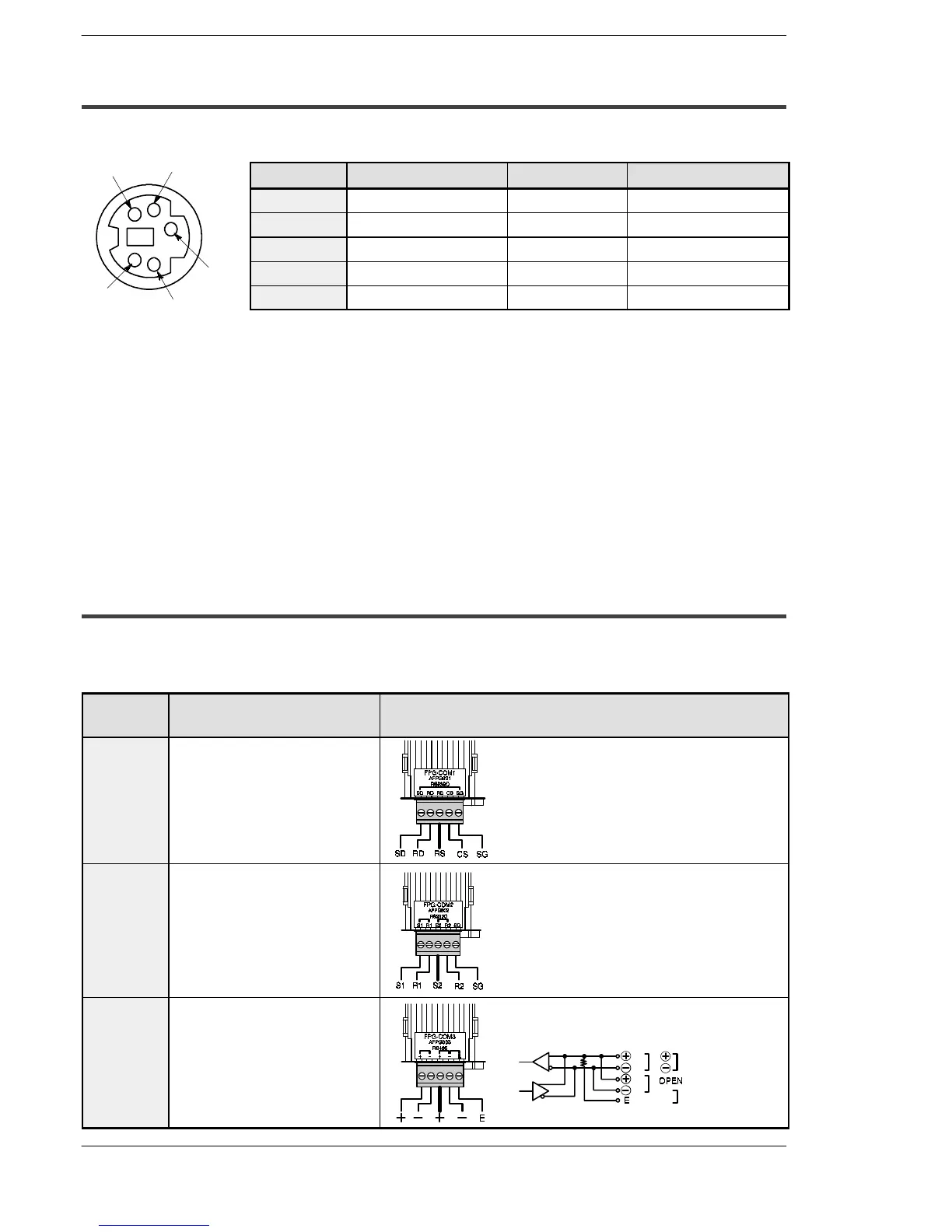
2.1.2 Tool Port Specification
A commercial mini-DIN 5-pin connector is used for the Tool port on the control unit.
Pin no. Signal name Abbreviation Signal direction
1
Signal Ground SG —
2
Transmitted Data SD Unit → External device
3
Received Data RD Unit ← External device
4
(Not used) — —
5
+5V +5V Unit → External device
Figure 10: FPΣ Parts and Functions (Tool port)
The following are the default settings set when the unit is shipped from the factory. The
system registers should be used to change these.
- Baud rate 9600 bps......
- Character bit 8 bit...
- Parity check Odd parity....
- Stop bit length 1 bit..
2.1.3 Communication Cassette
The detachable communication cassette (optional) can be selected from among the
three types shown below.
Type Applicable communication
function
Terminal layout diagram
1-channel
RS232C
type
Computer link
General-purpose serial
communication
SD: Transmitted Data (Output)
RD: Received Data (Input)
RS: Request to Send (Output)
CS: Clear to Send (Input)
SG: Signal Ground
2-channel
RS232C
type
Computer link
General-purpose serial
communication
S1: Transmitted Data (Output) (COM.1)
R1: Received Data (Input) (COM.1)
S2: Transmitted Data (Output) (COM.2)
R2: Received Data (Input) (COM.2)
SG: Signal Ground (COM.1 and 2)
1-channel
RS485 type
Computer link
General-purpose serial
communication
PLC link
General
station
Terminal
station
Short
1
3
5
4
2

 Loading...

