FPΣ
10.2 Communication Parameter Settings
10 - 11
Link areas consist of link relays and link registers for PLC link and used with
respective control units.
The link relay which can be used in an area for PLC link is maximum 1,024
points, and the link register is maximum 128 words.
Tip
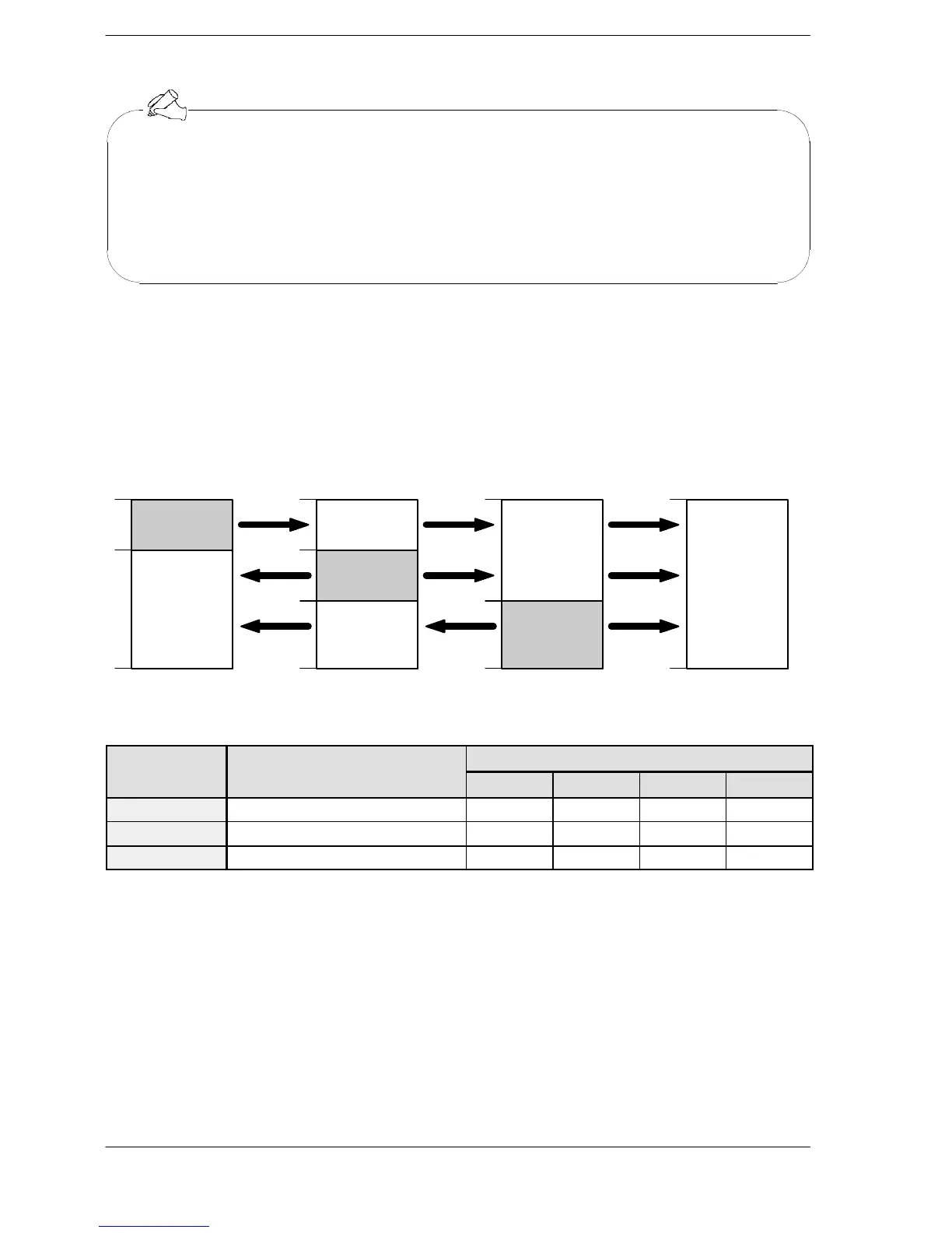
Example of link area allocation
The areas for PLC link is divided into transmitted areas and received areas. The link
relays and link registers are transmitted from the transmitted area to the received area
of a different FPΣ. Link relays and link registers with the same numbers as those on the
transmission side must exist in the received area on the receiving side.
Link relay allocation
No.1 No.1 No.1
No.2 No.2
No.3No.3No.3
No.2
WL0
19
20
63
WL0
19
20
63
WL0
63
WL0
63
39
40
39
40
Receivedarea
Transmitted
area
Receivedarea
Transmitted
area
Transmitted
area
FPΣ
(Unit No. 1)
FPΣ
(Unit No. 2)
FPΣ
(Unit No. 3)
FPΣ
(Unit No. 4)
Receivedarea
Receivedarea
Receivedarea
Figure 209: Example of link area allocation
System register
No. Name Set value of various control unit
No. 1 No. 2 No. 3 No. 4
No. 40 Range of link relay used for PLC link 64 64 64 64
No. 42 Starting no. for link relay transmission 0 20 40 0
No. 43 Link relay transmission size 20 20 24 0

 Loading...

