FPΣ
Communication Function 3 PLC Link Function
10 - 12
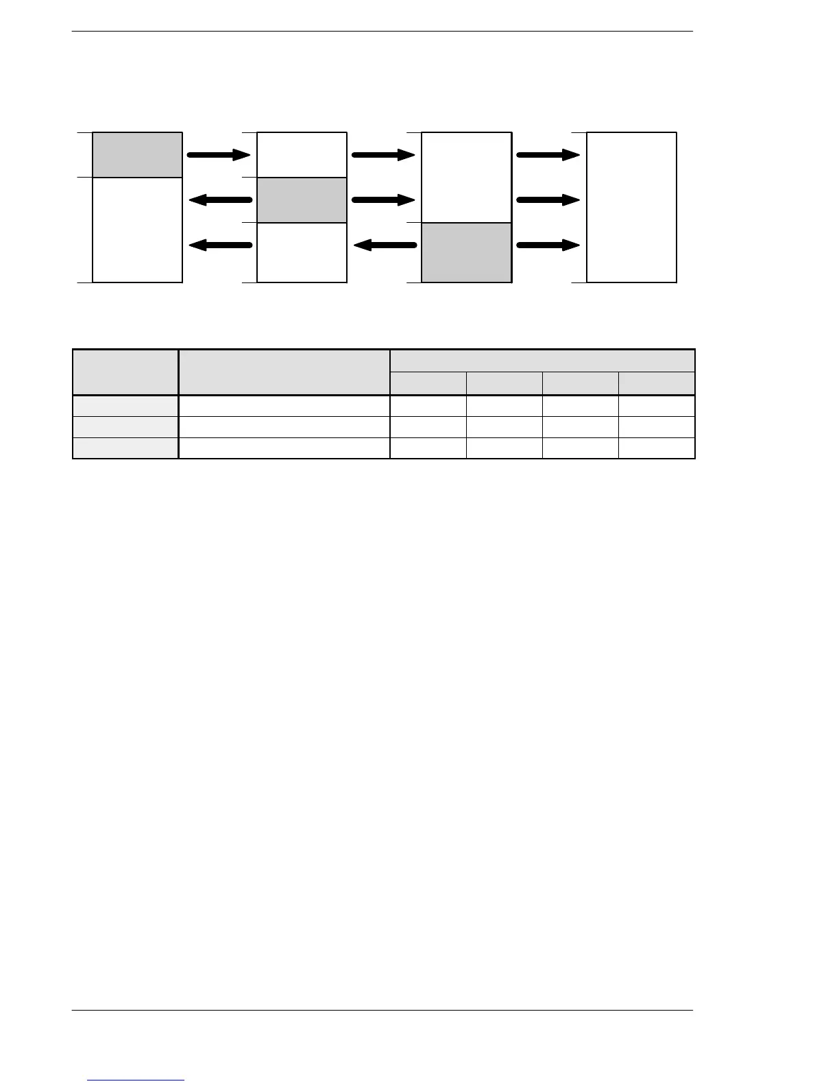
Link register allocation
No.1 No.1 No.1
No.2 No.2
No.3No.3No.3
No.2
LD0
39
40
127
LD0
39
40
127
LD0
127
LD0
127
79
80
79
80
Transmitted
area
Receivedarea
Transmitted
area
Transmitted
area
Receivedarea
FPΣ
(Unit No. 1)
FPΣ
(Unit No. 2)
FPΣ
(Unit No. 3)
FPΣ
(Unit No. 4)
Receivedarea
Receivedarea
Receivedarea
Figure 210: Example of link register allocation
System register
No. Name Set value of various control unit
No. 1 No. 2 No. 3 No. 4
No. 41 Range of link register used for PLC link 128 128 128 128
No. 44 Starting no. for link register transmission 0 40 80 0
No. 45 Link register transmission size 40 40 48 0
When link areas are allocated as shown above, the No. 1 transmitted area can be
transmitted to the No. 2, No. 3 and No. 4 received areas. Also, the No. 1 received area
can receive data from the No. 2 and No. 3 transmitted areas. No. 4 is allocated as a
received area only, and can receive data from No. 1, No. 2, and No. 3, but cannot
transmit it to other unit.

 Loading...

