FPΣ
Communication Function 3 PLC Link Function
10 - 4
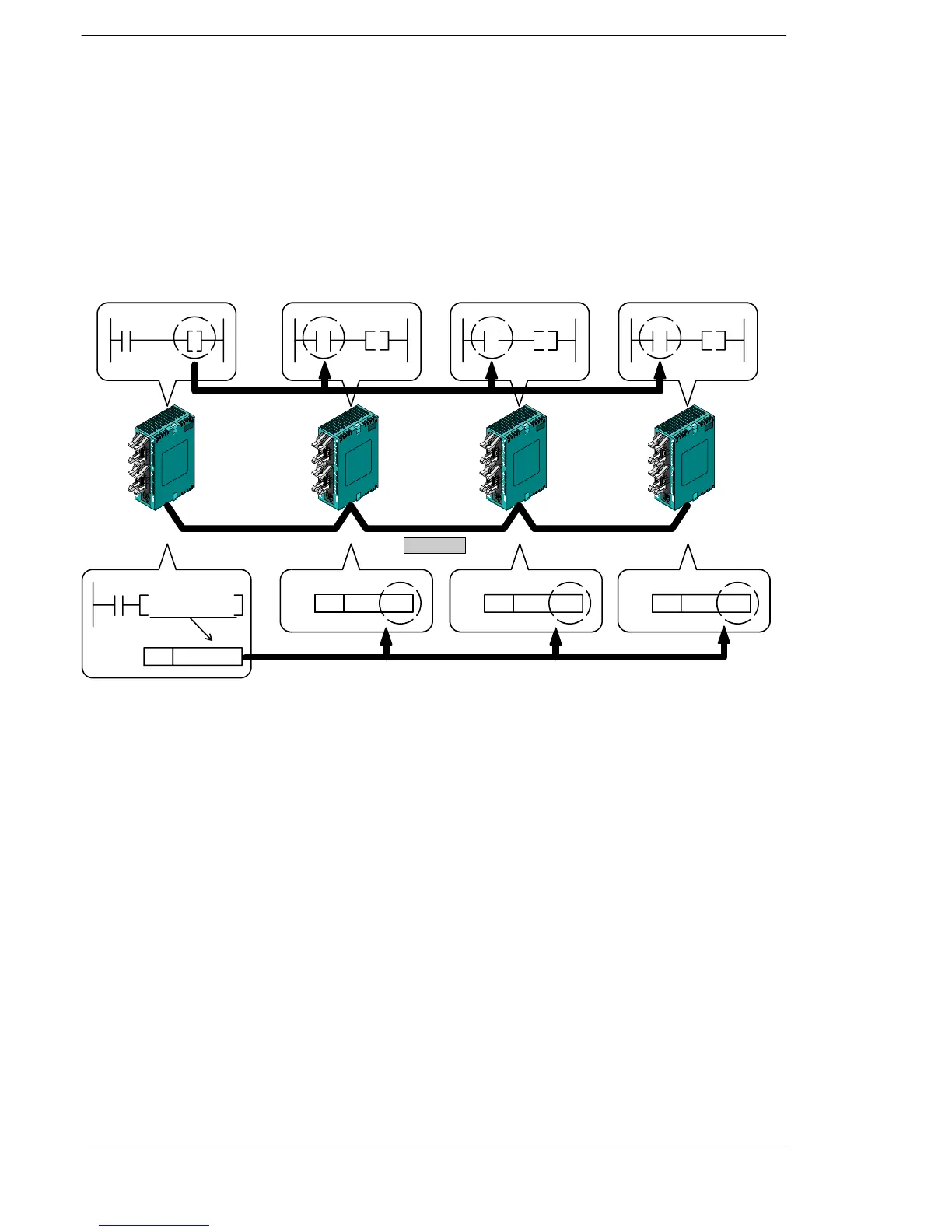
Overview of PLC link operation
Link relay: Turning on a link relay contact in one PLC turns on the same link relay
in all of the other PLCs on the same network.
Link register:If the contents of a link register in one PLC are changed, the values of
the same link register are changed in all of the PLCs on the same
network.
Link relay
R0
L0
L0
Y0
L0
Y0
L0
Y0
R0
F0, MV, K100, LD0
LD 0
100
LD 0
100
LD 0
100
LD 0
100
RS485
FPΣFPΣFPΣFPΣ
If the link relay L0 for the unit (No. 1) is turnedon, the status change is fed back to the ladder programs of other
units, and the Y0 of the other units is output.
No. 2 Link register
No. 3 Link register
No. 4 Link register
No. 1 Link register
Link register
If a constant of 100 is written to the LD0 of unit No. 1, the contents of LD0 in unit No. 2 are also changed to a
constant of 100.
Figure 202: FPΣ Overview of PLC link operation

 Loading...

