FPΣ
High-speed Counter and Pulse Output Functions
6-32
Positioning control instruction (F174) (Data table control)
The positioning performs according to the specified data table in order.
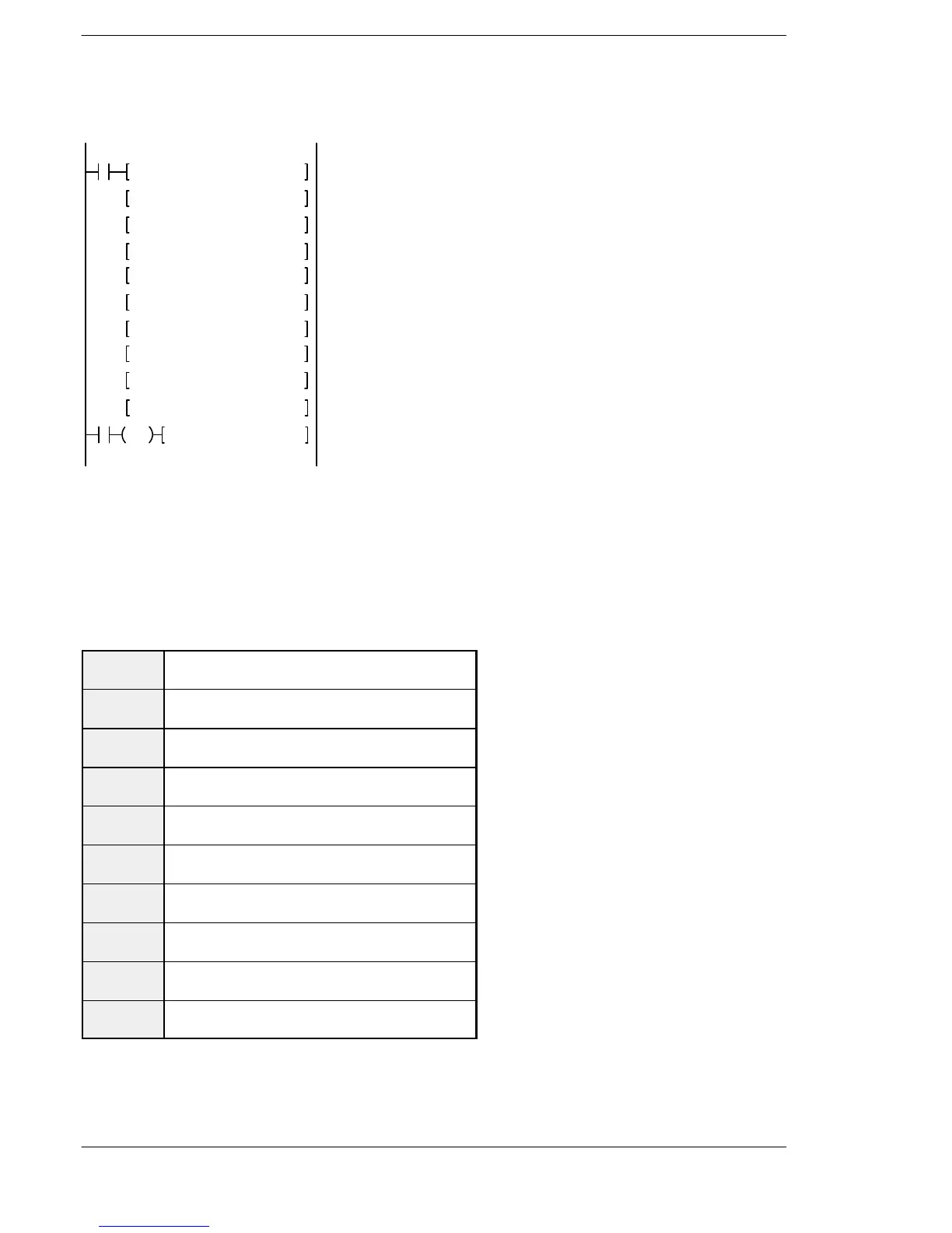
R0
F1 DMV , H 1200, DT400
F1 DMV , K 1000, DT402
F1 DMV , K 1000, DT404
F1 DMV , K 2500, DT406
F1 DMV , K 2000, DT408
F1 DMV , K 5000, DT410
F1 DMV , K 5000, DT412
Control code: “H1200”
Frequency 1: 1,000Hz
Target value 1: 1,000 pulses
Frequency 2: 2,500Hz
Target value 2: 2,000 pulses
Frequency 3: 5,000Hz
Target value 3: 5,000 pulses
R10
DF F174 SP0H,DT400,K0
F1 DMV , K 0, DT418
Pulse output control
Output pulse stops
F1 DMV , K 1000, DT414
F1 DMV , K 2000, DT416
Frequency 4: 1,000Hz
Target value 4: 2,000 pulses
When the execution condition R10 goes on, pulses are output from Y0 at a frequency
of 1,000 Hz, and positioning begins.
At the point when 1,000 pulses have been counted, the frequency switches to 2,500
Hz.Positioningisthen carried out sequentially inaccordancewiththe valuesof thedata
table, until it stops at the data table containing the pulse output stop value (K0).
When the program is run, the data table and pulse output diagram are as shown below.
Positioning data table
DT400
DT401
Control code * 1 :H 1200
DT402
DT403
Frequency 1 *2 :1000 Hz
DT404
DT405
Target value 1 *3 :1000 pulses
DT406
DT407
Frequency 2 :2500 Hz
DT408
DT409
Target value 2 :2500 pulses
DT410
DT411
Frequency 3 :500 Hz
DT412
DT413
Target value 3 :5000 pulses
DT414
DT415
Frequency 4 :1000 Hz
DT416
DT417
Target value 4 :2000 pulses
DT418
DT419
Pulse output stop setting :K0

 Loading...

