FPΣ
High-speed Counter and Pulse Output Functions
6-46
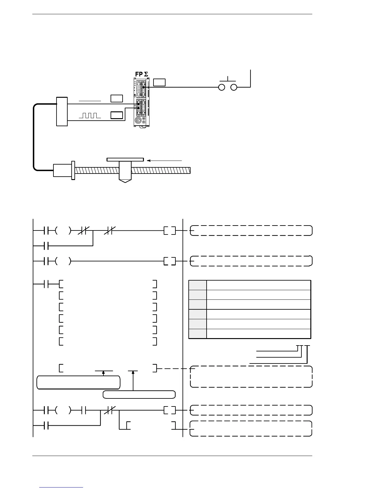
Relative value positioning operation (minus direction)
When X9 turns on, the pulse is output from CCW output “Y1” of specified channel CH0.
Y1
Y0
0 V (24 V DC)
X9
Pulse output CW
Pulse output CCW
Motor driver
(- side)
Motor
(+ side)
8000 pulses
Start input (-)
Figure 109: FPΣ Sample program - relative value positioning operation (– direction)
R903A
R20
R22
DF
X9 R20
R903A
R22
T0 R22
DF/
R20
DF
R20 R21
R21
Positioning operation running
Positioning operation start
F1 DMV H 1100 ,DT 100
F171 SPDH DT 100 ,K 0
F1 DMV K 1000 ,DT 102
F1 DMV K 6000 ,DT 104
F1 DMV K 300 ,DT 106
F1 DMV K -8000 ,DT 108
F1 DMV K 0 ,DT 110
TMX 0, K 10
Program
Positioning data table
Pulse output instruction (table-shaped control)
The data table headed by DT100 is used and
pulses are output from CH0.
The data table headed by DT100
is used.
Pulses are output from CH0.
Positioning done pulse (1 second)
0.1 s type timer
Setting K10 and using it as a 1-second timer
H11
Duty 1/4 (25%)
48 Hz to 100 kHz
Incremental CW and CCW
* Control code
DT100
DT101
DT102
DT103
DT104
DT105
DT106
DT107
DT108
DT109
DT110
DT111
Control code *: H 1100
Initial speed: 1,000 Hz
Maximum speed: 6,000 Hz
Acceleration time: 300 msec
Target value (Movement amount) :-8,000 pulses
Pulse stop
00
Figure 110: FPΣ Sample program - relative value positioning operation (program)

 Loading...

