FPΣ
High-speed Counter and Pulse Output Functions
6-54
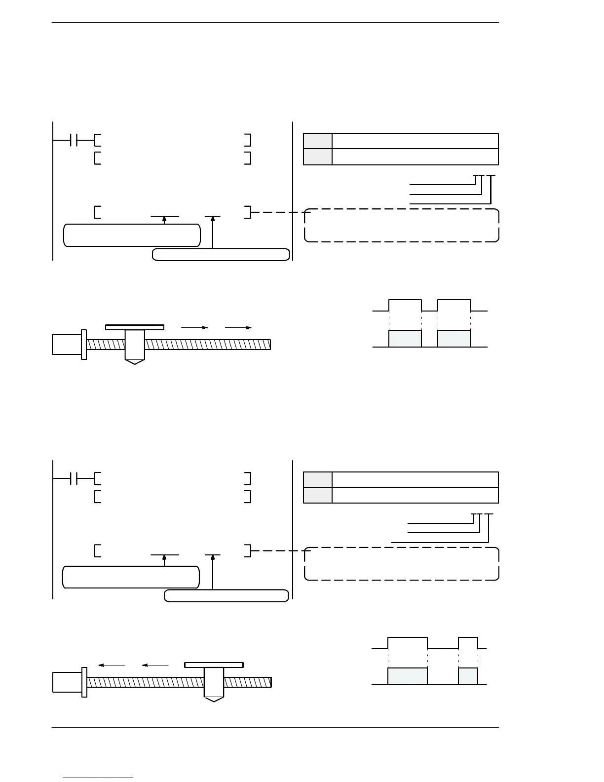
JOG operation (plus direction)
While X8 is in the on state, a pulse is output from CW output “Y0” of specified channel
“CH0”.
XB
F1 DMV H 1110 ,DT 300
F1 DMV K 300 ,DT 302
F172 PLSH DT 300 ,K 0
DT300
DT301
DT302
DT303
Control code *: H 1110
Frequency (speed): 300 Hz
The data table headed by DT300
is used.
Data table
H11
Duty 1/4 (25%)
48 Hz to 100 kHz
Addition counting CW
* Control code
Pulse output instruction (JOG operation)
The data table headed by DT300 is used and
pulses are output from CH0.
Program
Pulses are output from CH0.
10
Figure 121: FPΣ Sample program - JOG operation (+ direction) (program)
on
off
XB (JOG command)
300Hz
0Hz
Y0 (Pulse)
(- side)
Motor
(+ side)
Pulse output diagram
Figure 122: FPΣ Sample program - JOG operation (pulse output diagram)
JOG operation (minus direction)
While XC is in the on state, apulse is output from CCWoutput “Y1”of specifiedchannel
“CH0”.
XC
F1 DMV H 1121 ,DT 310
F1 DMV K 300 ,DT 312
F172 PLSH DT 310 ,K 0
DT310
DT311
DT312
DT313
Control code *: H 1121
Frequency (speed): 300 Hz
Data table
H11
Duty 1/4 (25%)
48 Hz to 100 kHz
Subtraction counting CCW
* Control code
Pulse output instruction (JOG operation)
The data table headed by DT310 is used and
pulses are output from CH0.
Program
The data table headed by DT310
is used
Pulses are output from CH0.
21
Figure 123: FPΣ Sample program - JOG operation (– diagram) (program)
on
off
XC (JOG command)
300Hz
0Hz
Y1 (Pulse)
(- side)
Motor
(+ side)
Pulse output diagram
Figure 124: FPΣ Sample program - JOG operation (pulse output diagram)

 Loading...

