FPΣ
9.2 Overview of Communication with External Devices
9-13
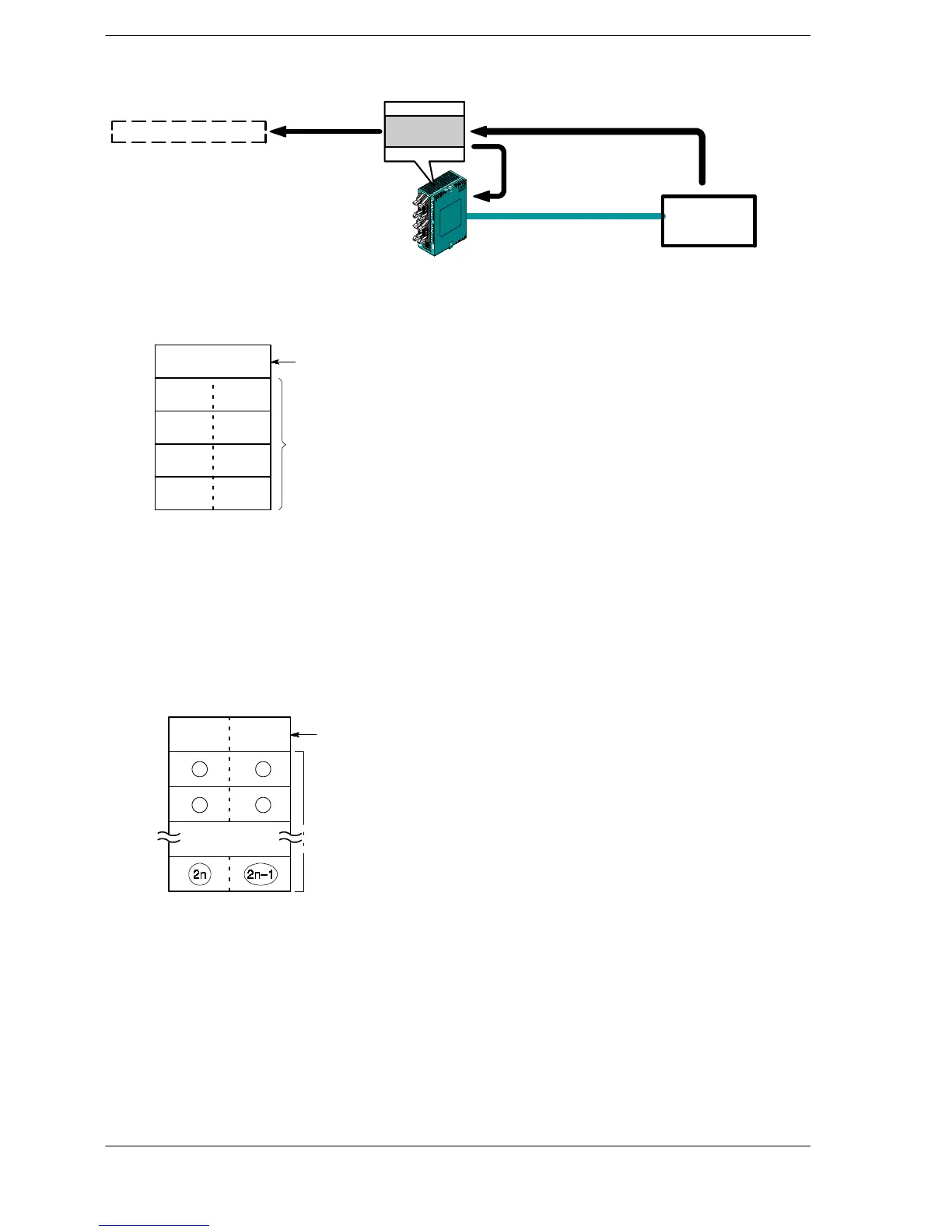
Explanatory diagram
“H4142434445464748”
FPΣ
Data register (DT)
Device with
RS232 port
Data receiving
Received
buffer
Reception done (R9038: on)
Reception ready (R9038: off)
Data reading
Figure 177: FPΣ Data reception explanatory diagram
DT200 to DT204 are used as the reception
buffer. System register settings are as fol-
lows:
- System register 416: K200
- System register 417: K5
Reception buffer when
receptioniscompleted.
DT201 H42(B) H41(A)
DT202 H44(D) H43(C)
DT203 H46(F) H45(E)
DT204 H48(H) H47(G)
DT200
Data table for reception (received buffer)
This shows the status of the data table when the above program is run.
The received number of
bytes is stored as data is
stored.
Received data is stored in
order from the lower-order
byte.
K8
Figure 178: FPΣ Data table for reception (received buffer)
Explanation of data table
Data sent from an external device connected to the RS232C port is stored in the data
registers that have been set as the reception buffer.
(Word) 0
The number of bytes
received is stored in
this area.
Reception data storage area
(The circled numbers indicate
the order of storage.)
1
2
n
12
34
Figure 179: FPΣ Data table for reception
Data registers are used for the reception buffer. Specify the data registers in system
registers 416 to 419.
The number of bytes of data received is stored in the starting address of the reception
buffer. The initial value is “0”.
Received data is stored in the received data storage area in order from the lower-order
byte.

 Loading...

