FPΣ
9.3 Connection Example with External Devices
9-21
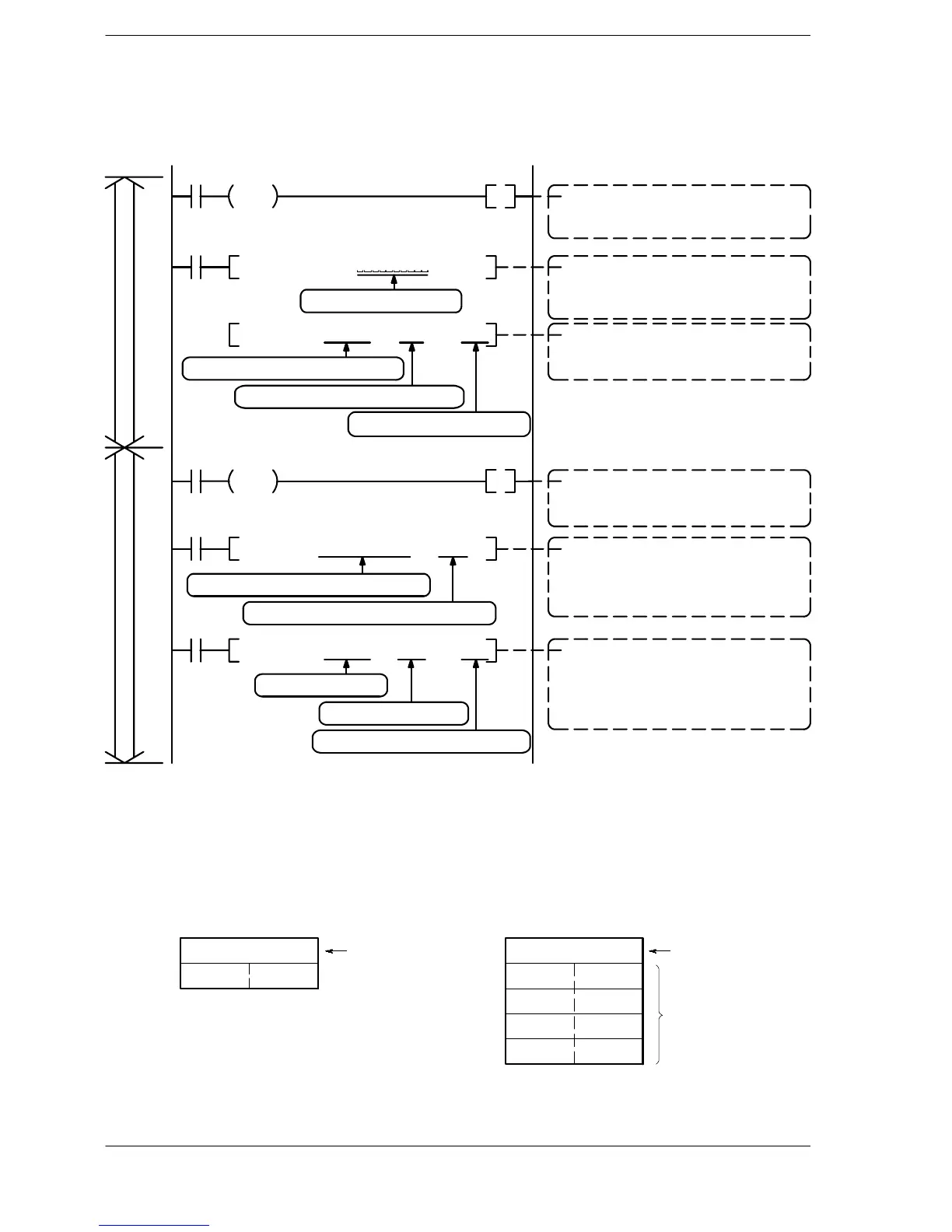
Sample program
In the following example, the Micro-Imagechecker is connected to the COM. 1 port.
R0
DF
R10
F95 ASC ,
R10
M %S , DT101
F159 MTRN
, DT 100 , K2 , K1
R9038
DF
, D201 , DT204 , DT0
R11
F10 BKMV
R11
R11
, DT 100 , K0 , K1F159 MTRN
TransmissionReception
Data transmission command
The internal relay “R10” is turned on at the
timing of the transmission condition “R0”.
Data conversion
The start command “%S” character is con-
verted to ASCII code, and written to DT101 to
DT106.
Data transmission
The data in the transmission buffer is sent
from the COM. 1 port
Reception done detection
The internal relay “R11” is turned on at the
reception done contact “R9038” timing.
Retrieving received data
The received data in the received buffer is
read from the area in which it is stored (from
DT201) and sent to DT0.
Preparing to receive the next data
To prepare to receive the next data, the F159
instruction resets the buffer writing point and
turns off the reception done contact “R9038”,
based on the empty data.
Ten spaces inserted
With DT100 as the transmission buffer
the contents consisting of two bytes of it
are sent from COM. 1 (K1) port.
Starting from DT100
the contents of 0 bytes
are sent from the COM. 1 (K1) port.
The 4-word contents from DT201 to DT204
are written to data registers DT0 to DT3.
Figure 185: FPΣ Sample program (for micro-imagechecker)
The various buffer statuses
The following shows the statuses of the send and received buffers when the sample
program is run.
Transmission buffer
Number of
bytes to be
transmitted
(Statuses before
transmission)
DT100
DT101
K2
H53 (S)
DT204
H25 (%)
DT200
DT201
DT202
DT203
Reception buffer
K7
Received
number of
bytes
Received data is
stored in order from
the lower-order byte.
H30 (0) H31 (1)
H32 (2) H31 (1)
H34 (4) H33 (3)
H35 (5)
(Statuses when
reception is completed)
Figure 186: FPΣ Various buffer statuses

 Loading...

