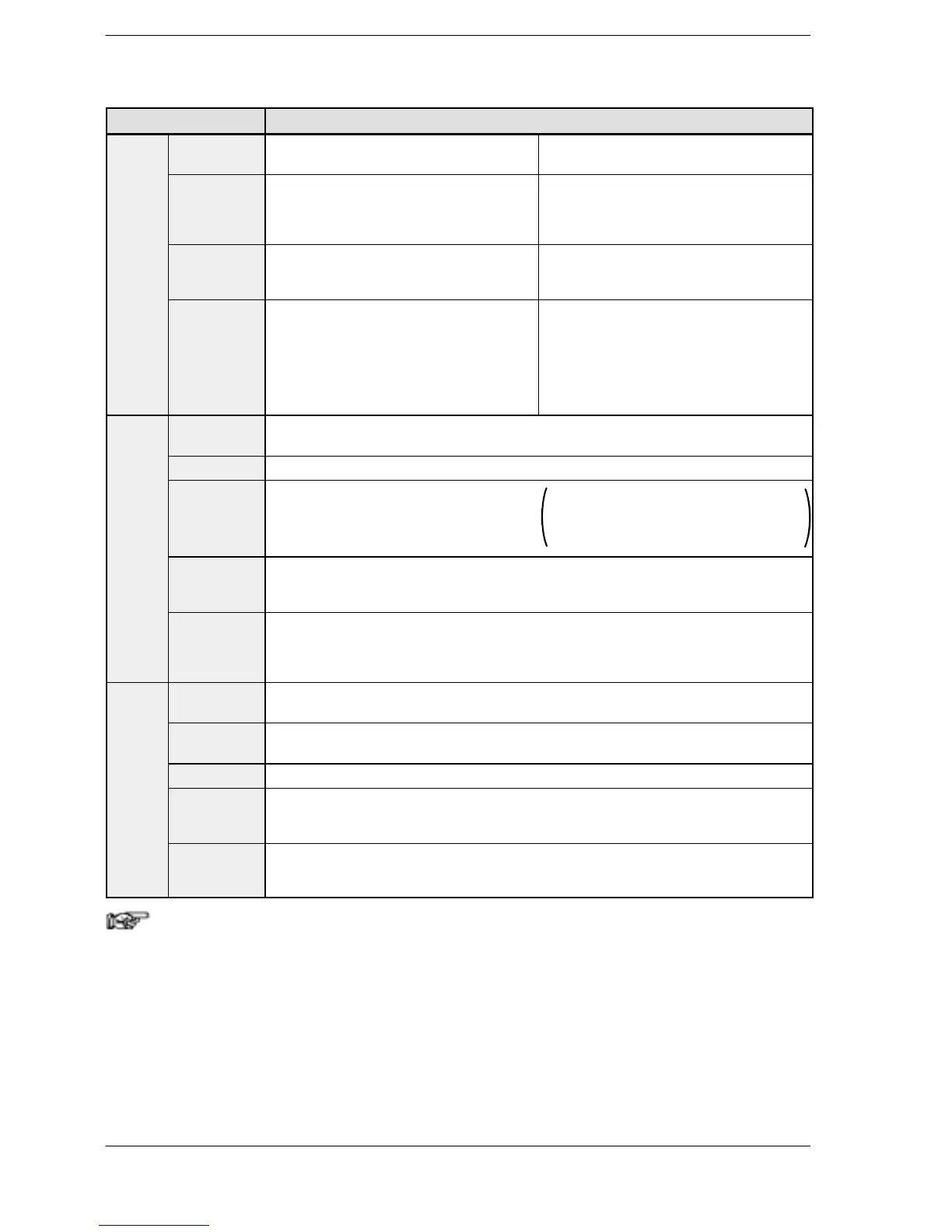
Input point
number
When using single-phase: Four channels
maximum
When using 2-phase: Two channels
maximum
counter
Maximum
counting
speed
When using single-phase:
for 1 channel: 50 kHz max. (x1 ch)
for 2 channels: 30 kHz max. (x2 ch)
for 3 or 4 channels: 20 kHz max. (x3 to 4ch)
When using 2-phase:
for 1 channel: 20 kHz max. (x1 ch)
for 2 channels: 15 kHz max. (x2 ch)
Input mode When using single-phase:
Addition input,
Subtraction input
When using 2-phase:
Two-phase input, One input,
Direction distinction input
Input
contact used
(* Note1)
When using single-phase:
X0: count input (ch0)
X1: count input (ch1)
X2: reset input (ch0, ch1)
X3: count input (ch2)
X4: count input (ch3)
X5: reset input (ch2, ch3)
When using 2-phase:
X0, X1: count input (ch0)
X2: reset input (ch0)
X3, X4: count input (ch2)
X5: reset input (ch2)
Pulse
output
Output point
number
Two independent points (simultaneous output possible)
Outputmode CW and CCW mode, Pulse and Sign mode
Maximum
output
frequency
When using 1 channel: 100 kHz max. (x1 ch)
When using 2 channels: 60 kHz max. (x2 ch)
When using linear interpolation function:
Max. 100 kHz
When using circular interpolation function:
Max. 20 kHz
High-speed
counter used
(* Note 2)
Two-phase ch0 or ch2
Input/Output
contact used
(* Note 1)
X2 or X5: Home input
Y0 or Y3: CW output or Pulse output
Y1 or Y4: CCW output or Sigh output
Y2 or Y5: Deviation counter reset output
PWM
output
Output point
number
Two points (Y0, Y3)
Output
frequency
1.5 to 12.5k Hz (at resolution of 1000), 15.6k to 41.7k Hz (at resolution of 100)
Output duty 0.0 to 99.9% (at resolution of 1000), 1 to 99% (at resolution of 100)
High-speed
counter used
(* Note 2)
Two-phase ch0 or ch 2
Output
contact used
(* Note 1)
Y0 or Y3
Notes
1) The contacts noted above cannot be allocated for more than
one function. Also, contacts that are not assigned to the
various functions can be used as general inputs/outputs.
Inputs X0 to X5 are pulse catch inputs, and can also be used
for interrupt input.
2) If using pulse output or PWM output, one channel of the
two-phase high-speed counter is used for each output point,
in each case. If only one pulse output point is being used,
either one point of the two-phase high-speed counter or three
points of the single-phase high-speed counter may be used.

 Loading...

