FPΣ
Specifications
13 - 46
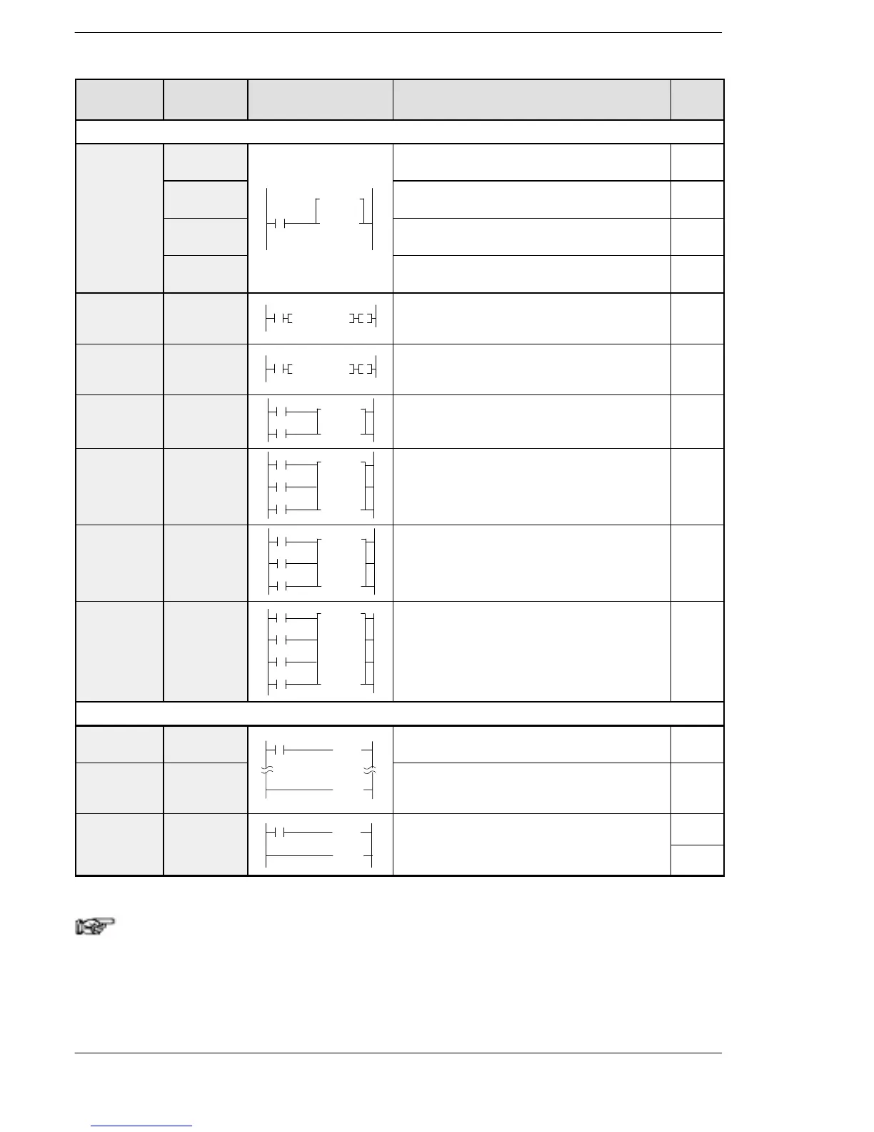
Name Boolean Symbol Description
Steps
(* Note)
Basic function instructions
On-delay
timer
TML After set value “n”× 0.001seconds, timer contact
“a” is set to on.
3 (4)
TMR
TMa n
After set value “n” × 0.01 seconds, timer contact
“a” is set to on.
3 (4)
TMX After set value “n” × 0.1 seconds, timer contact
“a” is set to on.
3 (4)
TMY After set value “n” × 1 second, timer contact “a”
is set to on.
4 (5)
Auxiliary
timer
(16-bit)
F137
(STMR)
Y,R,L
F137STMR,S,D
After set value “S” × 0.01 seconds, the specified
output and R900D are set to on.
5
Auxiliary
timer
(32-bit)
F183
(DSTM)
Y,R,L
F183DSTM,S,D
After set value “S” × 0.01 seconds, the specified
output and R900D are set to on.
7
Counter CT
Count
Reset
CT
n
Decrements from the preset value “n”. 3 (4)
UP/DOWN
counter
F118 (UDC)
UP/DOWN
Count
F118 UDC
Reset
S
D
Increments or decrements from the preset value
“S” based on up/down input.
5
Shift register SR
Data
Shift
SR WR n
Reset
Shifts one bit of 16-bit [word internal relay (WR)]
data to the left.
1
Left/right
shift register
F119
(LRSR)
Data
Shift
Reset
L/R
F119 LRSR
D1
D2
Shifts one bit of 16-bit data range specified by
“D1” and “D2” to the left or to the right.
5
Control instructions
Master
control relay
MC
(MC n)
Starts the master control program. 2
Master
control relay
end
MCE
(MCE n)
Master control area
Ends the master control program. 2
Jump JP
(JP n)
The program jumps to the label instruction and
continues from there.
2
Label LBL
(LBL n)

 Loading...

