FPΣ
Specifications
13 - 48
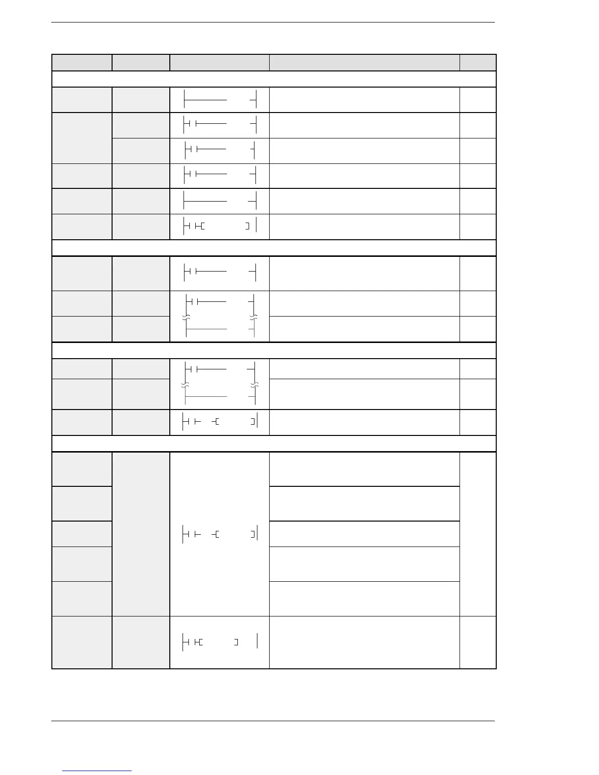
Name Boolean Symbol Description Steps
Step ladder instructions
Start step SSTP
(SSTP n)
The start of program “n” for process control 3
Next step NSTL
(NSTL n)
Start the specified process “n” and clear the pro-
cess currently operated. (Scan execution type)
3
NSTP
(NSTP n)
Start the specified process “n” and clear the pro-
cess currently operated. (Pulse execution type)
3
Clear step CSTP
(CSTP n)
Resets the currently operated process “n”. 3
Step end STPE
(STPE )
End of step ladder area 1
Clear multi-
ple steps
SCLR
SCLR n1, n2
Resets the currently operated processes “n1” to
“n2”.
5
Subroutine instructions
Subroutine
call
CALL
(CALL n)
Executes the specified subroutine. When return-
ing to the main program, outputs in the subrou-
tine program are maintained.
2
Subroutine
entry
SUB
(SUB n)
Indicates the start of the subroutine program “n”. 1
Subroutine
return
RET
(RET )
Ends the subroutine program. 1
Interrupt instructions
Interrupt INT
(INT n)
Indicates the start of the interrupt program “n”. 1
Interrupt
return
IRET
(IRET )
Ends the interrupt program. 1
Interrupt
control
ICTL
ICTL S1, S2
(DF)
Select interrupt enable/disable or clear in “S1”
and “S2” and execute.
5
Special setting instructions
Communica-
tion condi-
tions setting
SYS1 Change the communication conditions for the
COM port or tool port based on the contents spe-
cified by the character constant.
13
Password
setting
Change the password specified by the PLC
based on the contents specified by the character
constant.
Interrupt
setting
SYS1, M
(DF)
Set the interrupt input based on the contents
specified by the character constant.
PLC link
time setting
Set the system setting time when a PLC link is
used, based on the contents specified by the
character constant.
RS485
response
time control
Change the communication conditions of the
COM. port or tool port for RS485 based on the
contents specified by the character constant.
System
registers
“No. 40 to
No. 47”
changing
SYS2
SYS2, S, D1, D2
Change the setting value of the system register
for the PLC link function.
7

 Loading...

