FPΣ
5.3 Wiring of Input and Output
5-13
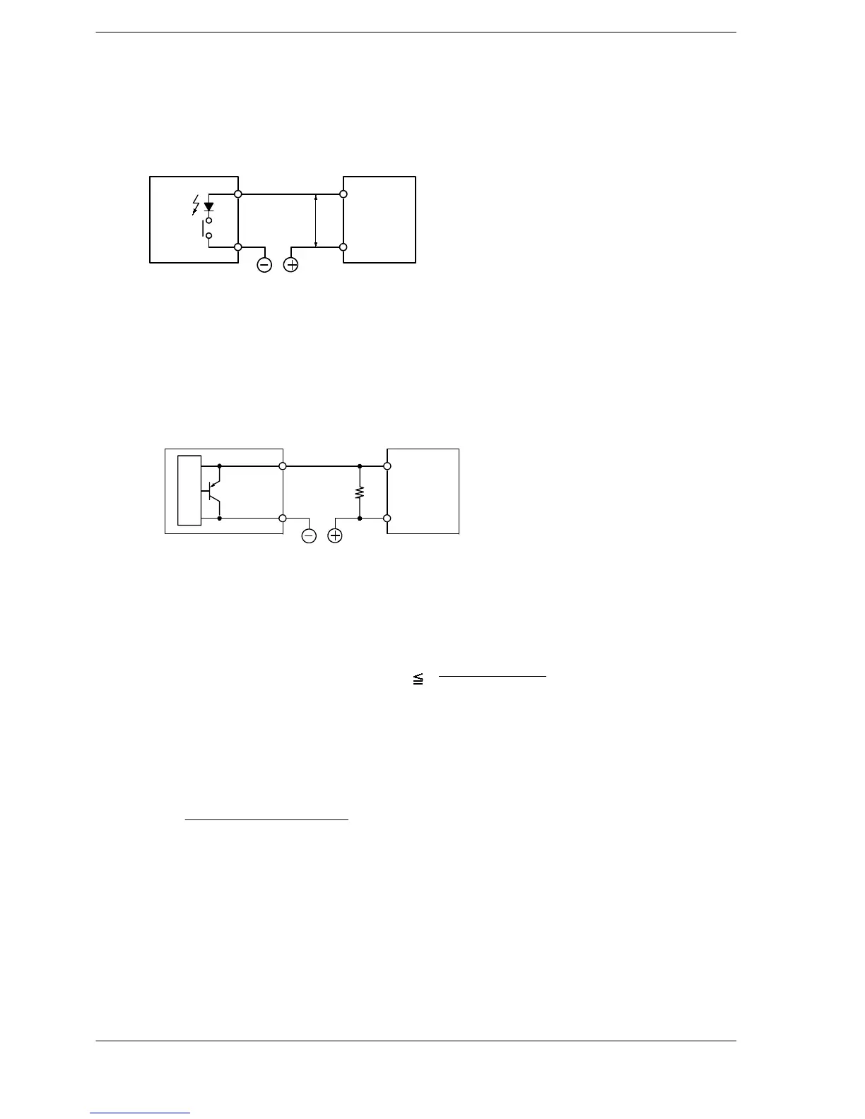
Precaution when using LED-equipped lead switch
When a LED is connected in series to an input contact such as LED-equipped lead
switch, make sure that the on voltage applied to the PLC input terminal is greater than
19.2 V DC. In particular, take care when connecting a number of switches in series.
LED-
equipped
lead
switch COM
24 V
19.2 V
or more
LED
contact
Input terminal
FPΣ
Figure 43: FPΣ Precaution when using LED-equipped lead switch
Precaution when using two-wire type sensor
If the input of PLC does not turn off because of leakage current from the two-wire
type sensor “photoelectric sensor or proximity sensor”, the use of a bleeder resistor
is recommended, as shown below.
Two-wire
type sensor
Bleeder
resistor
COM
Input terminal
Internal
circuit
R
FPΣ
Figure 44: FPΣ Precaution when using two-wire type sensor
The off voltage of the input is 2.4 V, therefore, select the value of bleeder resistor “R” so that
the voltage between the COM terminal and the input terminal will be less than 2.4 V.
The input impedance is 5.6 kΩ.(I: Sensor’s leakage current (mA))
The resistance R of the bleeder resistor is: R
The formula is based on an input impedance of 5.6 kΩ. The input impedance varies depend-
ing on the input terminal number.
The wattage W of the resistor is:
In the actual selection, use a value that is 3 to 5 times the value of W.
13.44
(Power supply voltage)
2
R
(kΩ)
5.6 x I –2.4
W=

 Loading...

