RMC Ethernet Support
You must connect this interface to voltage-mode-PHY-compatible Ethernet magnetics. The
NI sbRIO-9607/9627 RMC Design Guide on ni.com/manuals provides design guidelines,
requirements for routing signals, and recommendations for appropriate magnetics and
connectors. The following specifications depend on a suitable RMC board design that follows
these guidelines and requirements.
Network interface 10Base-T, 100Base-TX, 1000Base-T Ethernet
Compatibility IEEE 802.3
Communication rates 10 Mbps, 100 Mbps, 1,000 Mbps auto-
negotiated, half-/full-duplex
RMC Ethernet LED Behavior
The RMC connector provides signals for implementing Ethernet LEDs on an RMC.
The GBE_ACT_LEDg signal indicates the link status and activity of the Ethernet connection,
as described in the following table.
Table 20. Ethernet Link Activity LED Behavior
Link State GBE_ACT_LEDg Behavior
No link Low
Link, but no activity High
Link with activity Toggling
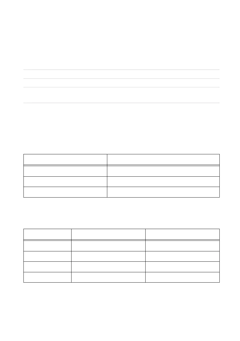
The GBE_SPEED_LEDg and GBE_SPEED_LEDy signals indicate the link speed of the
Ethernet connection, as described in the following table.
Table 21. Ethernet Speed LED Behavior
Link Speed GBE_SPEED_LEDg GBE_SPEED_LEDy
No link Low Low
10Base-T Low Low
100Base-TX High Low
1000Base-T Low High
C Series DIO
The C Series DIO lines provides up to two slots of C Series support on the RMC. All lines can
be connected directly to the 15-pin DSUB connector except for the 5 V power. The 5 V power
38 | ni.com | NI sbRIO-9607 User Manual