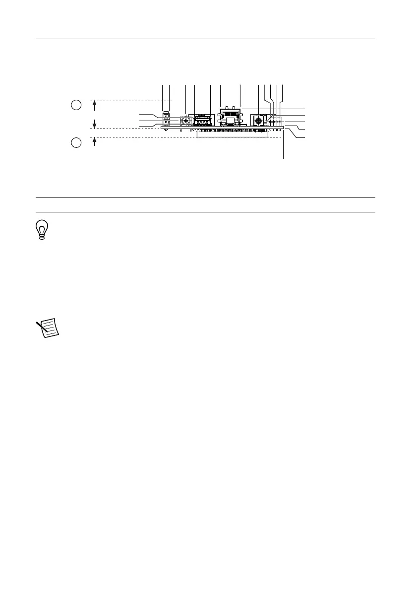
Figure 4. Front Dimensions in mm (in.)
0.00 (0.000)
15.64 (0.616)
6.16 (0.242)
5.34 (0.210)
2.16 (0.085)
0.0 (0.00)
95.21 (3.748)
89.81 (3.536)
76.82 (3.025)
70.02 (2.757)
57.52 (2.265)
49.73 (1.958)
33.99 (1.338)
19.50 (0.768)
10.16 (0.400)
7.62 (0.300)
5.08 (0.200)
2.54 (0.100)
8.76 (0.345)
6.32 (0.249)
3.66 (0.144)
18.16 (0.715)
6.15 (0.242)
1
2
1. Minimum Clearance for Latch on Mating Power Connector
Tip For two-dimensional drawings and three-dimensional models of the
sbRIO-9607, visit ni.com/dimensions and search by model number.
Maximum Component Heights
The primary side of the sbRIO-9607 is the top side of the PCB populated with the power and
Ethernet connectors. The secondary side is the bottom side of the PCB populated with the
RMC connector. The following figures show the maximum component heights for the
different regions of the primary and secondary sides.
Note In addition to the maximum component heights, you must also observe
minimum keepaway distances for adjacent PCBs and surfaces.
NI sbRIO-9607 User Manual | © National Instruments | 5