Table 17. RMC Connector Feature Set Compatibility (Continued)
Feature Set sbRIO-9605/06/23/26 sbRIO-9607 Future Design
Compatibility
GBE_MDI[0..3+/-] No Yes Not guaranteed
USB_MODE, USB_CPEN,
USB_VBUS
No Yes Not guaranteed
Dedicated C Series DIO No
2
Yes Not guaranteed
VIN_FILTERED No Yes Yes
RMC Connector Power Requirements
Use the following voltage pins to power the RMC:
• 5 V rail (pins 54, 60, 66, and 72), which provides a primary power source to the RMC
• 3.3 V_AUX (pin 48), which provides an auxiliary power source to the RMC
• FPGA_VIO (pins 234 and 240), which provides I/O power for the FPGA I/O pins
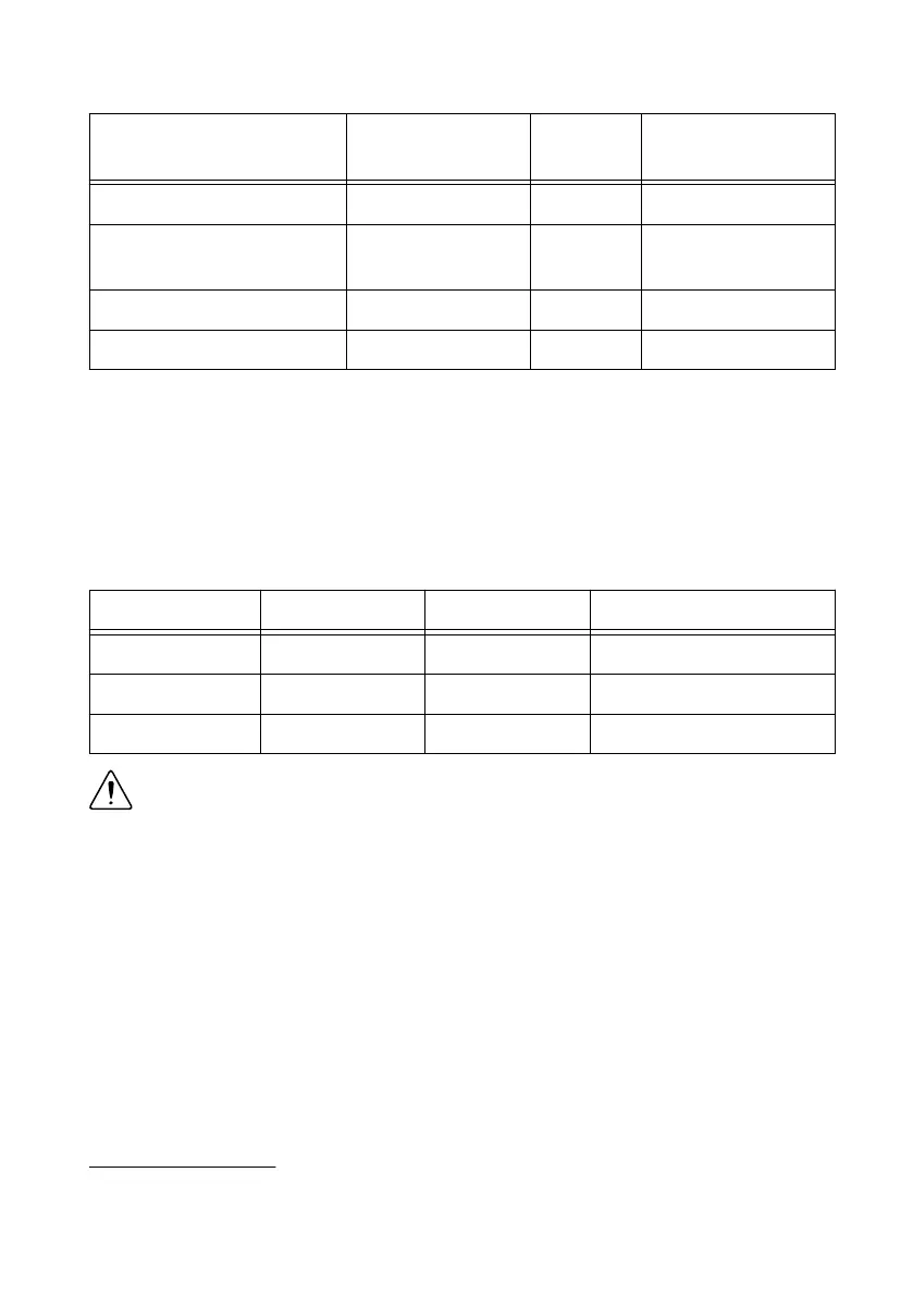
The following table lists the requirements for each rail on an RMC connector.
Rail Voltage Tolerance Maximum Current Maximum Ripple and Noise
5 V ± 5% 1.5 A 50 mV
3.3V_AUX ± 5% 0.33 A 50 mV
FPGA_VIO (3.3 V) ± 5% 0.33 A 50 mV
Caution Ensure that your RMC does not source any current onto any of the power
pins and can tolerate 5 V and FPGA_VIO coming up in any order.
RMC Connector Electrical Characteristics
Each pin in an RMC connector conforms to a particular I/O standard. On the sbRIO-9607, the
LVTTL
3.3V
I/O standard meets the input and output logic levels defined in the NI sbRIO-9607
Specifications on ni.com/manuals.
RMCs with FPGA I/O pins that require an explicit pull-up or pull-down should use the values
listed in the following table.
2
The sbRIO-9605/06/23/26 supports C Series I/O using the NI 9693.
36 | ni.com | NI sbRIO-9607 User Manual