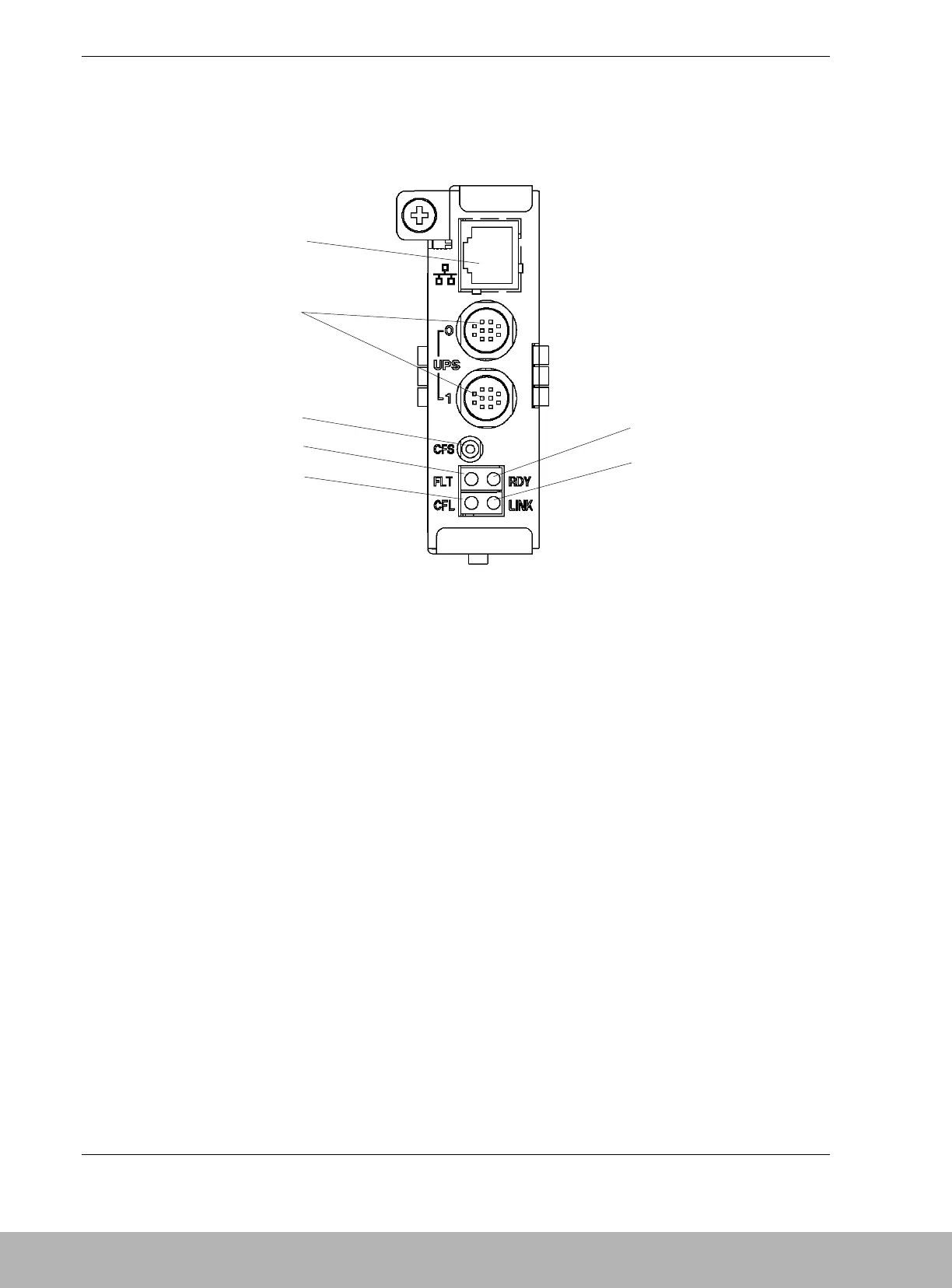
1-22 Disk Array Unit Overview
SVP Service Processor
Figure 1-12 shows the features and indicators located on the rear of the SVp service
processor.
A Ether
(10/100BASE-T)
connector
(Ethernet connector)
B UPS connector
(UPS0/UPS1
connector)
For the configuration in which the device receives AC power from UPS
(uninterruptible power supply), the signal cable connector is used to
connect the DAU with the UPS.
C CACHE FLUSH
switch
(pushbutton
switch)
This switch, when pushed, saves the cache data to the disk.
D FLT LED (FAULT
LED)
This LED, when lit, shows a fault occurred in the SVR.
When this LED flashes during the scheduled stop, the Write Back error
has occurred.
E CFL LED This LED, when lit, indicates that data is being saved from the cache to
the disk.
F RDY LED
(READY LED)
This LED, when lit, shows the service processor (SVR) is
operating in a normal state.
GLINK LED (TX/RX
LED)
This LED lights green when transmission/reception of data is being
transferred to and from a network.
Figure 1-12. SVP Service Processor