Disk Array Unit Overview 1-23
Disk Enclosure Controller
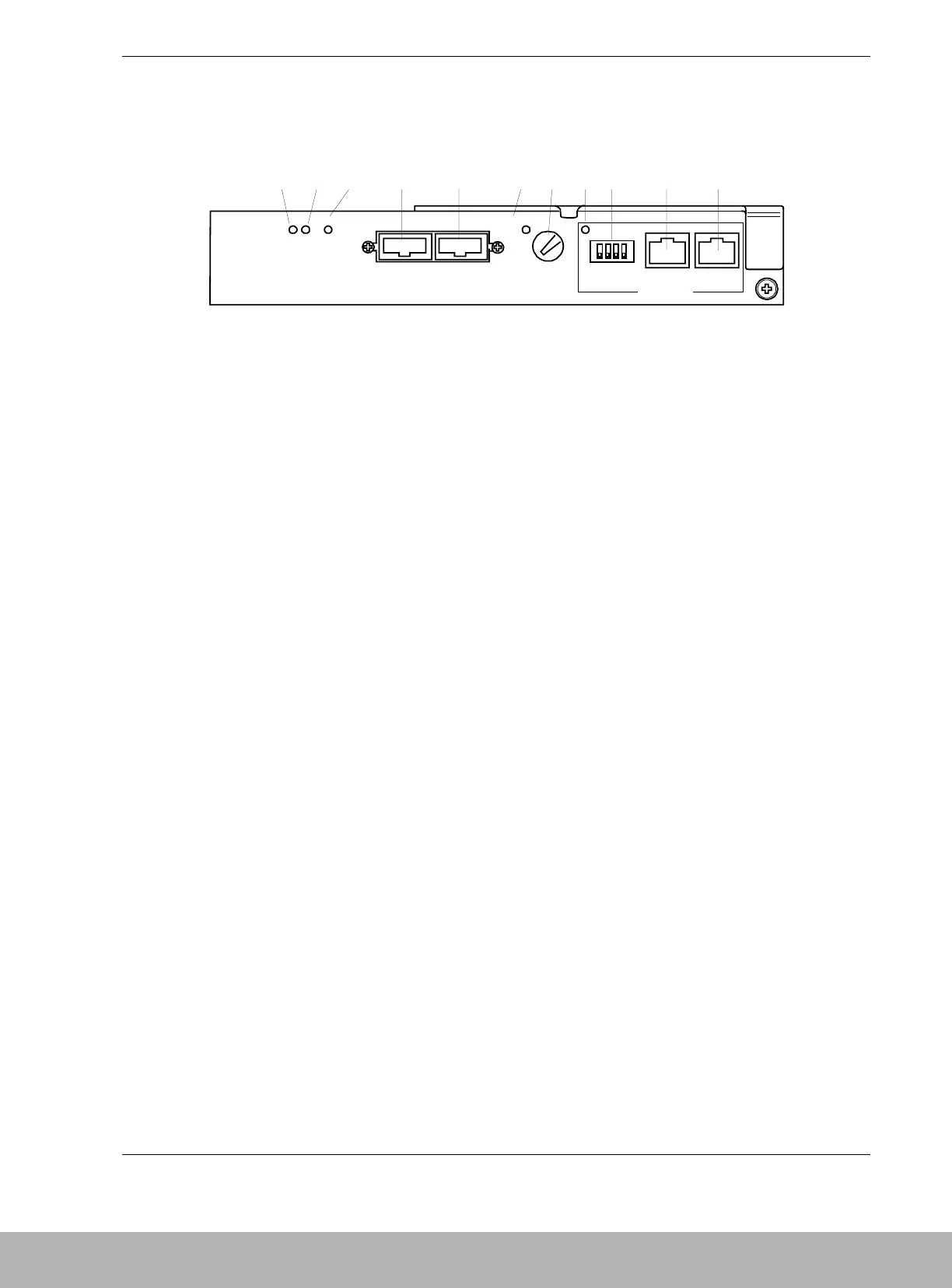
Figure 1-13 shows the features and indicators located on the rear of the Disk Enclosure
controller.
ABC D E FGHI J K
RDY FLT
FC - OUT FC - IN
DIAG RDY
DIAG ID
PORT1
ENC ID
DE - DIAG
PORT0
A READY LED
(green)
The READY LED lights green while the controller operates normally.
The LED blinks during the self-test or initialization, just after power-on.
B FAULT LED
(orange)
The FAULT LED lights orange if a fault occurs in the controller.
CFC-OUT
LINKUP LED
(2
nd
DE LINK)
This LED lights green indicating the FC interface with a second DE is
operable. A second DE is not currently available with the S1300 DAU.
D FC connector (for
connection with a
2
nd
DE)
This connector is used to connect the Disk Enclosure (DE) with a
second DE. A second DE is not currently available with the S1300 DAU.
E FC connector (for
connection with
Disk Array Unit)
This connector is used to connect the Disk Enclosure (DE) with the Disk
Array Unit.
FFC-IN
LINKUP LED
(DAU LINK)
This LED lights green indicating the FC interface with the DAU is
operable.
G ENC ID Switch This switch sets the ID address of the DE Controller. This switch must
be set to 1 in the DE.
H DE-DIAG LED
(green)
The DE-DIAG LED lights green when the controller has a valid
diagnostic connection to the DAU.
I DIAG ID Switches The four DIP switches are set to OFF (down) for the first DE.
J DE-DIAG
connector
The DE-DIAG connector is provided to connect a cable to a second DE
for diagnosing (monitoring) functions in the second DE. A second DE is
not currently available with the S1300 DAU.
KDAU-DIAG
connector
The DAU-DIAG connector is provided to connect a cable to the DAU for
diagnosing (monitoring) functions in the DE.
Figure 1-13. Disk Enclosure Controller Features and Indicators